MCS Equipment General Description (Hardware)
Requested by: |
Empresarios Agrupados |
|---|---|
Doc. Code: |
3151_MCS_0004 |
Editor: |
AO, PLG |
Approved by: |
Introduction
This document describes the characteristics of the hardware used in the Main Control System (MCS).
Technical description of the hardware used in the MCS
This chapter briefly describes the components followed by a table with its main characteristics. Components are organized by function: distributed I/O, heaters, switches…
Switches
Ethernet Switch: CISCO IE-3000 8TC
The Cisco® Industrial Ethernet 3000 (IE3000) is a switch that provide a secure switching infrastructure for harsh environments.
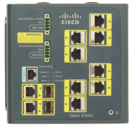
3000 Switch Technical details
Specification |
|---|
8 Ethernet 10/100 ports and 2 Dual-Purpose Uplinks (Each Dual Purpose Uplink port has one 10/100/1000 Ethernet Port and one SFP based Gigabit Ethernet port, one port active) |
Each switch supports two (2) Cisco IE3000-8FE modules, one (1) Cisco IE3000-8FX module, or one (1) Cisco IE3000-8FE module and one (1) Cisco IE3000-8FX module |
Performance |
|---|
Wire-speed switching |
128 MB DRAM |
64 MB Flash memory |
Configurable up to 8000 MAC addresses |
Configurable up to 255 IGMP groups |
Configurable maximum transmission unit (MTU) of up to 9000 bytes, with a maximum Ethernet frame size of 9018 bytes (Jumbo frames) for bridging on Gigabit Ethernet ports, and up to 1998 bytes for bridging of Multi-protocol Label Switching (MPLS) tagged frames on both 10/100 and 10/100/1000 ports |
Power Consumption |
|
|---|---|
Maximum power consumption |
31 W |
Input Voltage and Currents supported |
18-60VDC, (Cisco IE3000-4TC and Cisco IE3000-8TC) 85-265VAC/88-300VDC, 1.3-0.8A, 50-60 Hz (with addition of Cisco IE3000-PWR) |
Power Rating |
0.05 kVA |
Environmental data |
|
Operating temperature |
-40 to 70 ºC |
Storage temperature |
-25 to 70 ºC |
Operating relative humidity |
10 to 95% (condensing) |
Operating altitude |
Up to 3049 m |
Storage altitude |
Up to 4573 m |
Mechanical Data |
|
Dimensions |
|
Height |
152 mm |
Width |
147 mm |
Height |
112 mm |
Weight |
3.6 kg |
Standards and Certifications |
|
Standard safety certifications |
UL to UL 60950, Third Edition C-UL to CAN/CSA C22.2 No. 60950-00, Third Edition TUV/GS to EN 60950:2000 CB to IEC 60950 with all country deviations NOM to NOM-019-SCFI CE Marking |
Industrial safety certifications |
UL 508 CSA 22.2 / 142 EN60204-1 EN61010-1 EN61131-2 EN61140 |
Mechanical stability |
Shock—15g (Operational), 30g (Nonoperational) |
EMC Interface Immunity |
IEC61000-4-2 [Criteria A—Class 2] IEC61000-4-3/ENV50204 [Criteria A] IEC61000-4-4 [Criteria A / Criteria B] IEC61000-4-5 [Criteria B] IEC61000-4-6 [Criteria A] |
Standard Electromagnetic Emissions Certifications |
FCC Part 15 Class A EN 55022: 1998 (CISPR22) EN 55024: 1998 (CISPR24) VCCI Class A AS/NZS 3548 Class A CE CNS 13438 Class A MIC |
Industrial Electromagnetic Emissions Certifications |
EN 50081-2 EN 50082-2 EN 61131-2 EN 61326-1 CISPR11 |
Industry Specifications |
EC 61850-3 (Substations) IEEE1613 (Substations) NEMA TS-2 (ITSs) EN50155 (Railway) ODVA Common Industrial Protocol IEEE 1588v2 PROFINET IO |
Hazardous Locations |
UL 1602 Class 1, Div 2 A-D CSA 22.2 / 213 Class 1, Div 2 A-D IEC 60079-15 EN 50021—Class 1, Zone 2 |
Mean time between failures |
|
Time |
338801 hours |
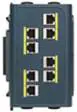
Ethernet Switch extension: CISCO IEM-3000 8TMC
Expansion copper Module for Cisco IE-3000-4TC, IE-3000-8TC, IE-3000-4TC-E, and IE-3000-8TC-E switches, eight 10/100 TX ports.
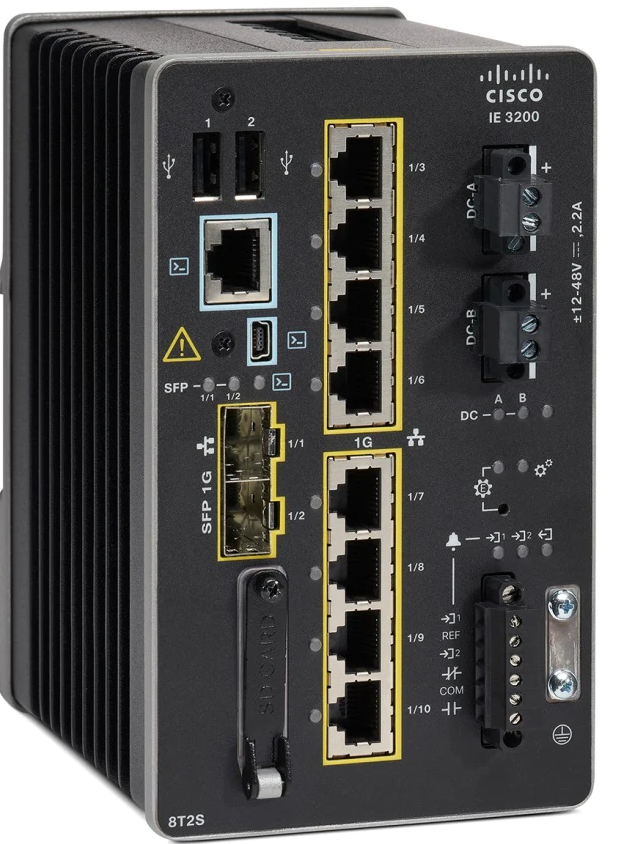
Ethernet Switch: CISCO IE-3200 8T2S_E
The Cisco Catalyst® IE3200 Rugged Series ushers in mainstream adoption of Gigabit Ethernet connectivity in a compact form factor for a wide variety of extended enterprise and industrial applications.
3200 Switch Technical details
Features |
|
|---|---|
Forwarding rate |
Line rate for all ports and all packet sizes |
Number of queues |
8 |
Unicast MAC addresses |
8K |
Internet Group Management Protocol (IGMP) multicast groups |
1K |
No. of VLANs |
256 |
Spanning Tree Protocol (STP) instances |
128 |
Access Control Entries (PACL/VACL/RACL) |
3K |
DRAM |
2 GB |
Flash (User Accessible) |
1.5 GB |
SD card capacity1 |
4 GB |
Jumbo Frames |
8996 bytes |
Cabinet Temperature control system
Controller: Watlow RMC
Technical details are general data of RMC family
Module for thermal system management. It contains multiple temperature inputs, PID or on/off control loop & high ampere power output options.
Watlow Controller Technical details
Inputs |
|
|---|---|
Universal input |
|
Type |
Thermocouple, grounded or ungrounded sensor. RTD 2 or 3 wire, platinum, 100 and 1000 Ω Potentiometer: 0 to 1200 Ω |
Input impedance |
> 20 MΩ |
Source resistance |
Max. of 2 kΩ |
Process |
0 – 20 mA @ 100 Ω or 0 – 10 V DC @ 20kΩ input impedance |
Current range |
0 – 50 mA @ 100 Ω input impedance |
Response time |
1 s max., accuracy ±1 mA typical |
Thermistor Input |
|
Input range |
0 to 40 kΩ, 0 to 20 kΩ, 0 to 10 kΩ, 0 to 5 kΩ |
Linearization curve |
Built – in |
Digital input |
|
Update rate |
10 Hz |
Max. voltage |
36 V DC @ 3 mA |
Min. high state |
3 V @ 0.25 mA |
Max. low state |
2 V |
Dry Contact Input |
|
Update rate |
10 Hz |
Min. open resistance |
10 kΩ |
Max. closed resistance |
50 Ω |
Max. short circuit |
13 mA |
Calibration Accuracy |
|
Accuracy and sensor conformity |
±0.1% of span, ±1ºC @ calibrated ambient Tº & line voltage |
Type R, S, B |
0.2% |
Type T below -50ºC |
0.2% |
Calibration ambient temperature |
25ºC (±3ºC) |
Accuracy span |
540ºC min |
Temperature stability |
±0.1ºC/ºC change in ambient |
Environmental data |
|
Operating Temperature |
-18 – 65ºC |
Storage Temperature |
-40 – 85ºC |
Ambient Relative Humidity |
0 – 90%, non condensing |
Environmental data |
|
Operating Temperature |
-18 – 65ºC |
Storage Temperature |
-40 – 85ºC |
Ambient Relative Humidity |
0 – 90%, non condensing |
Electrical data |
|
Module’s supply voltage |
20.4 to 30.8 V AC/DC, 50/60 Hz |
Voltage tolerance |
-5% / +5% |
External supply requirements |
Class 2 or SELV rating |
Power consumption |
7 W, 14 VA |
Mechanical Data |
|
Installation |
DIN-rail mounting |
Standards and Certifications |
|---|
UL®/EN 61010 Listed, C-UL® C22.2 #61010ANSI/ISA 12.12.01-2007 Class 1, Div. 2-Group A, B, C, D temperature code T4 (optional) |
UL® 1604 Class 1, Div. 2 (optional) |
EN 60529 IP20 |
UL® 50, NEMA 4X, EN 60529 IP66; 1/16 DIN remote user interface (RUI) |
CSA 610110 CE |
FM Class 3545 on limit control versions |
Communication module: Watlow RMA A3
This module adds fieldbus protocols, memory and data logging to the RMC.
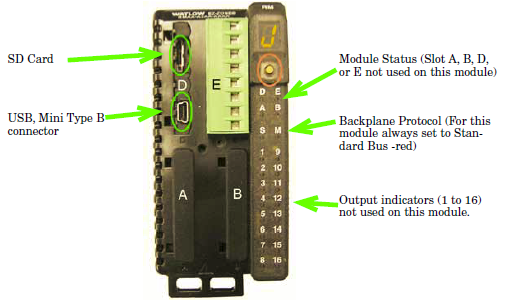
Watlow communication Technical details
General Data |
|
|---|---|
Maximum system configuration |
One RMA with up to 16 RM modules |
Memory card |
Removable micro SD physical size |
Data logging |
Storage in micro SD, CSV file type |
Peripheral port |
|
Serial standard bus |
Yes |
EIA 232/485 Modbus RTU |
Optional |
Ethernet/IP, Modbus TCP |
Optional |
DeviceNET |
Optional |
Profibus DP |
Optional |
USB |
Optional (mass storage) |
Environmental data |
|
Temperature |
|
Operating temperature |
-18 – 65 ºC |
Storage temperature |
-40 – 85 ºC |
Relative humidity |
0 – 90%, non condensing |
Fire/Shock |
Rail mount modules need to be installed in fire/shock protection enclosures, such as NEMA 1 type unless all connections are class 2 or SELV |
Electrical data |
|
Voltage supply range |
20.4 – 30.8 V (AC/DC), ±5% |
Power |
4 W, 9 VA |
Mechanical data |
|
Dimensions |
|
Length |
147 mm |
Width |
52 mm |
Height |
116 mm |
Housing |
IP 20 |
Standards and Certifications |
|---|
UL/EN 61010; c_UL C22.2 #61010 |
ANSI/ISA 12.12.01-2007 Class 1, Div. 2-Group A, B, C, D Temperature code T4 |
EN 60529 IP20 |
FM Class 3545 |
UL 50, Type 4X indoor use |
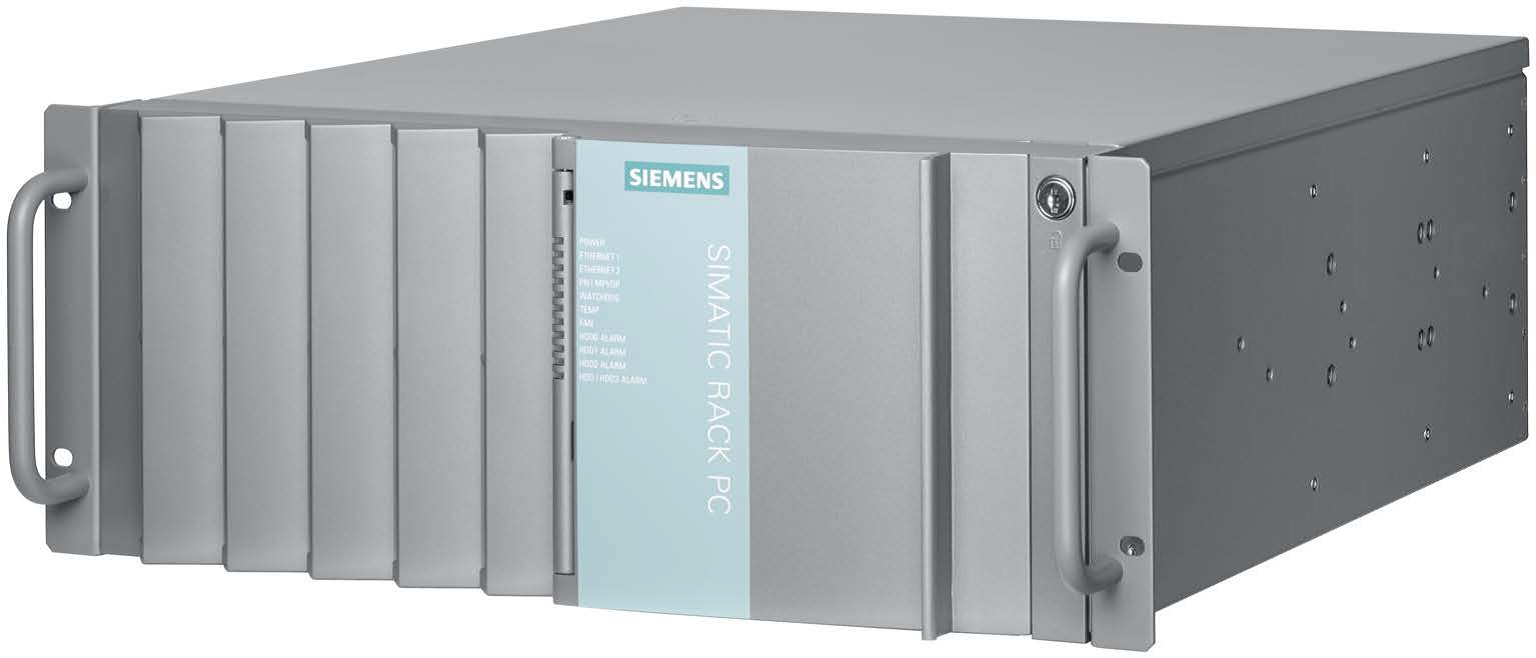
Mount Control Computer
Simatic IPC847D
For the MCC a Simatic IPC847D industrial computer is used, with the following characteristics:
General Data |
|
|---|---|
Order Number |
6AG4114-2ND30-0XX6 |
Processors and Mainboards: |
Xeon E3-1275 v3 (4C/8T, 3.5(3.9) GHz, 8MB Cache, TB, VT-x, VT-d, AMT; 2x Gb Ethernet, 2x DisplayPort, 1xDVI-I , 2x USB 3.0 rear, 2x USB 2.0 rear, 1x USB 3.0 front, 2x USB 2.0 front, 1x USB 3.0 internal, 1x COM1) |
Drives (SATA): |
RAID1, 1 TB (2x 1 TB HDD, data mirroring); Internally mounted, 0.5g Vibration, 5g shock |
Main Memory: |
8 GB DDR3 SDRAM (2x 4 GB), dual channel; |
Ethernet |
2 × Ethernet interface (RJ-45) Ethernet 1: WGI217LM, AMT-capable 6, supports jumbo frames up to 9014 bytes Ethernet 2: Intel WGI210IT, supports jumbo frames up to 9014 bytes |
Type of Housing and Exchangeable Media: |
Housing painted; |
Extensions (Hardware): |
1xCoOM (RS232, 9-pin), graphics onboard; |
Country-specific types / Power Supplies: |
2x 110/230V Redundant power supply |
This PC runs on CentOS 7 64bits operating system and LabVIEW will be used for the EUI.
Supermicro server
For the MCC a supermicro server is used, with the following characteristics:

General Data |
|
|---|---|
Chassis: |
Supermicro Server rack 1U with redundant power supply, chassis server CSE-813MFTQC-R407CB |
Processor: |
AMD EPYC RAPHAEL 4344P |
Disks: |
3x M.2 NVMe Enterprise 960GB (with Supermicro Low Profile 2x PCIe Gen 4 Hybrid NVMe/SATA M.2 RAID Boot Storage Adapter, AOC-SLG4-2H8M2-O) |
Main Memory: |
2x 16 GB DDR5 |
Ethernet: |
2× 1Gb Ethernet interface (RJ-45) |
Country-specific types / Power Supplies: |
2x 110/230V Redundant power supply |
This server runs on Alma 9 64bits operating system, the installation guide can be found here.
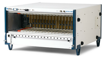
PXIs
Chassis: NI PXIe-1086
The NI PXIe-1086 is a 18-slot chassis with PXI Express platform. It incorporates hot-swappable, redundant AC power supplies as well as hot-swappable, front-accessible, redundant cooling fans.
NI PXIe-1086 Technical details
General Data |
|
|---|---|
Number of slots |
18 |
PXI bus type |
PXI Express PXI Hybrid Compatible |
Number of hybrid peripheral slots |
16 |
Maximum system bandwidth |
12 GB/s |
Compatible with 3U PXI & CompactPCI modules |
Yes |
Optional front or rear rack mountable |
Yes |
Integrated controller |
No |
Electrical Data |
|
Total available power |
855 W |
Input voltage range |
100 V – 240 V AC |
Input frequency range |
47 Hz – 63 Hz |
Field-replaceable power supply |
Yes |
Remote power inhibit control and voltage monitoring |
Yes |
DC output |
+3.3 V, max. 50 A (single), 60 A (dual) +5 V, max. 40 A (single), 49 A (dual) +12 V, max. 50 A (single), 62 A (dual) -12 V, max. 4 A (single), 4 A (dual) +5 Vaux, max. 1.5 A (single), 1.5 A (dual) |
Cooling Data |
|
Auto fan |
|
Sound pressure level |
57 dBA |
Sound power |
63.3 dBA |
High fan |
|
Sound pressure level |
69 dBA |
Sound power |
79.3 dBA |
Auto/High fan selector |
Yes |
Number of fans |
6 |
Environmental data |
|
Vibration IEC-60068-2-27 & IEC-60068-2-64 |
|
Operational shock |
30 g |
Random vibration |
5 – 500 Hz, 0.3 g |
Temperature IEC-60068-2-1 & IEC-60068-2-2 |
|
Operating temperature |
0 – 50 ºC |
Storage temperature |
-40 – 71 ºC |
Humidity IEC-60068-2-56 |
|
Operating relative humidity |
5 – 95 % |
Storage relative humidity |
5 – 95 % |
Max. altitude |
4600 m |
Mechanical data |
|
Dimensions |
|
Length |
476.5 mm |
Width |
467.1 mm |
Height |
268.7 mm |
Weight |
|
One power supply |
14.3 kg |
Dual power supply |
17.1 kg |
Standards and Certifications |
|
Safety |
IEC 61010-1, EN 61010-1 UL 61010-1, CSA 61010-1 |
EMC |
EN 61326-1 (IEC 61326-1): Class A emissions; EN 55011 (CISPR 11): Group 1, Class A emissions AS/NZS CISPR 11: Group 1, Class A emissions FCC 47 CFR Part 15B: Class A emissions ICES-001: Class A emissions |
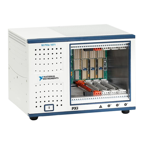
Chassis: NI PXIe-1071
The NI PXIe-1071 combines a 4-slot PXI Express backplane with a structural design optimized for maximum usability in a wide range of applications.
NI PXIe-1071 Technical details
Chassis Cooling |
|
|---|---|
Per slot cooling capacity |
38.25 W |
Module cooling system |
Forced air circulation (positive pressurization) through a 150 CFM fan with High/Auto speed selector |
Slot airflow direction |
Bottom of module to top of module |
Module cooling intake |
Bottom of chassis |
Module cooling exhaust |
Right side, rear, and top of chassis |
Power supply cooling system |
Forced air circulation through integrated fan |
Power supply cooling intake |
Front and left side of chassis |
Power supply cooling exhaust |
Rear of chassis |
Environmental |
|
Maximum altitude |
2,000 m (800 mbar) (at 25 °C ambient) |
Measurement Category |
II |
Pollution Degree |
2 |
For indoor use only |
|
Operating Environment |
|
Ambient temperature range |
0 to 50 °C (Tested in accordance with IEC-60068-2-1 and IEC-60068-2-2. Meets MIL-PRF-28800F Class 3 low temperature limit and MIL-PRF-28800F Class 2 high temperature limit.) |
Relative humidity range |
20 to 80%, non-condensing (Tested in accordance with IEC-60068-2-56.) |
Shock and Vibration |
|
Operational shock |
30 g peak, half-sine, 11 ms pulse (Tested in accordance with IEC-60068-2-27. Meets MIL-PRF-28800F Class 2 limits.) |
Random Vibration |
|
Operating |
5 to 500 Hz, 0.3 g_rms |
Non-operating |
5 to 500 Hz, 2.4 g_rms (Tested in accordance with IEC-60068-2-64. Non-operating test profile exceeds the requirements of MIL-PRF-28800F, Class 3.) |
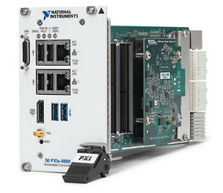
CPU: NI PXIe-8880
High-performance Intel Xeon E5-2618L v3 processor-based embedded controller for use in PXI Express systems. With the 2.3 GHz base frequency (3.4 GHz single-core, Turbo Boost mode) eight-core processor with up to 16 hyper threaded virtual cores and the triple-channel 1866 MHz DDR4 memory, this controller is ideal for processor-intensive RF, modular instrumentation, and DAQ applications.
NI PXIe-8880 Technical details
General Data |
|
|---|---|
Controller type |
Embedded |
PXI bus type |
PXI Express |
CPU |
Intel Xeon ES-2618L |
CPU clock frequency |
2.3 GHz (base), 3.4 GHz (single-core Turbo) |
Number of cores |
8 |
Memory |
8 GB (standard), 24 GB (max) |
Solid-State drive |
24 B or larger serial ATA |
Operating system |
Windows 7 |
Required slots |
4 |
Peripheral port |
|
Ethernet |
1000BaseT, 2 ports |
GPIB (IEEE 488.2) Interface |
Yes |
Serial ports (RS232) |
No |
Parallel |
No |
USB |
2.0 = 4, 3.0 = 2 |
Electrical Data |
|
Power |
+3.3 V, typ. 2.24 A, max. 2.96 A +5 V, typ. 2.44 A, max. 3.11 A +12 V, typ. 6.5 A, max. 8.7 A +5 Vaux, typ. 0.19 A, max. 0.23 |
Environmental data |
|
Vibration IEC-60068-2-27 & IEC 60068-2-64 |
|
Operational shock |
30 g |
Random vibration |
|
Operating |
5 – 500 Hz, 0.3 g |
Non-operating |
5 – 500 Hz, 2.4 g |
Temperature IEC-60068-2-1 & IEC-60068-2-2 |
|
Operating temperature |
0 – 50 ºC |
Storage temperature |
-40 – 71 ºC |
Humidity IEC-60068-2-56 |
|
Operating relative humidity |
10 – 90 % |
Storage relative humidity |
5 – 95 % |
Maximum altitude |
2000 m |
Mechanical data |
|
Dimensions |
Four-wide 3U PXI Express module |
Weight |
1.5 kg |
Standards and Certifications |
|
Safety |
IEC 61010-1, EN 61010-1 UL 61010-1, CSA 61010-1 |
EMC |
EN 61326-1 (IEC 61326-1): Class A emissions EN 55011 (CISPR 11): Group 1, Class A emissions EN 55022 (CISPR 22): Class A emissions EN 55024 (CISPR 24): Immunity AS/NZS CISPR 11: Group 1, Class A emissions AS/NZS CISPR 22: Class A emissions FCC 47 CFR Part 15B: Class A emissions ICES-001: Class A emissions |
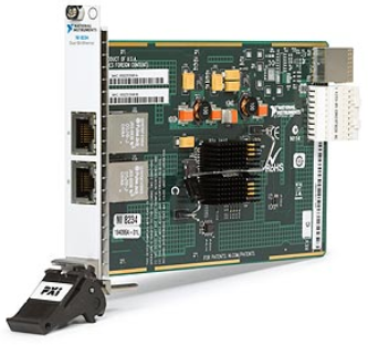
Dual Ethernet Port: NI PXIe-8234
Based on the Intel 82572EI gigabit controller.
Technical details
General Data |
|
|---|---|
Product family |
Frame grabbers |
Form factor |
PXI / PXI Express |
PXI bus type |
PXI Express PXI Hybrid Compatible |
Camera interface |
GigE Vision |
Operating system |
Windows |
Required slot |
1, supporting a x4 PCI connection |
Smart Camera |
|
Industrial protocol support |
Ethernet / IP Modbus / TCP TCP / IP |
Number of camera input ports |
2 |
Peripheral port |
|
Ethernet |
|
Interface |
2 x 10P10C modular jack |
Signaling |
1000Base-T |
Environmental data |
|
Temperature IEC-60068-2-1 & IEC-60068-2-2 |
|
Operating temperature |
0 – 55 ºC |
Storage temperature |
-40 – 70 ºC |
Humidity IEC-60068-2-56 |
|
Operating relative humidity |
10 – 90 %, non condensing |
Storage relative humidity |
5 – 95 %, non condensing |
Max. altitude |
2000 m |
Electrical Data |
|
Power |
3.3 V, typ. 0.375 A 5 V, typ. 0.36 A 1.8 V, typ. 1.19 A 5.2 W max. |
Mechanical data |
|
Dimensions |
|
Length |
160 mm |
Width |
100 mm |
Weight |
158 g |
Standards and Certifications |
|
Safety |
IIEC 60950-1, EN 60950-01 UL 60950-1, CSA 60950-1 |
EMC |
EN 61326 EMC requirements; Minimum Immunity EN 55011 Emissions; Group 1, Class A CE, C-Tick, ICES, and FCC Part 15 Emissions; Class A |
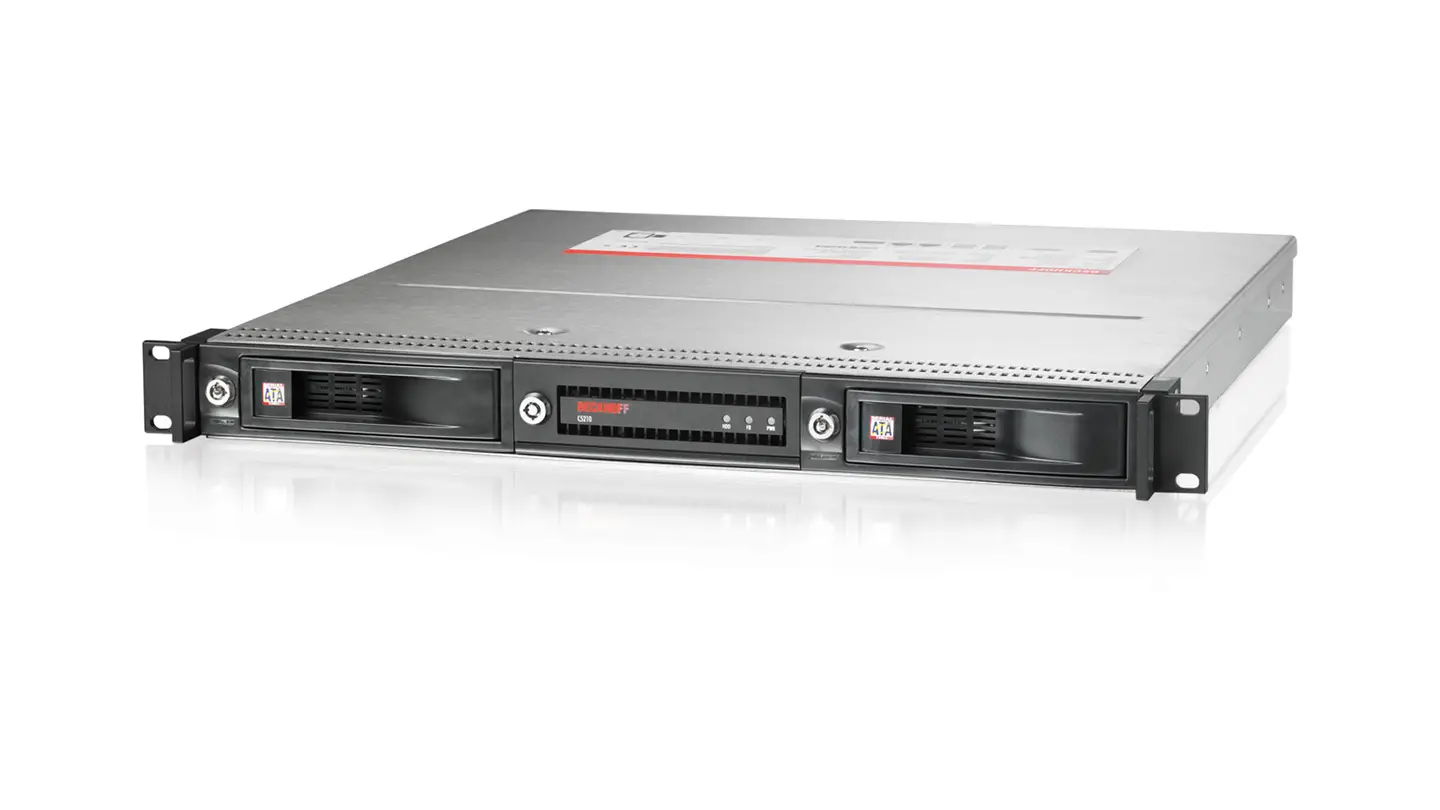
Beckhoff Industrial PC C5210-0040
The C5xxx Industrial PCs series is designed for 19-inch slide-in installation. They are equipped with maximum performance class components and are ideally suited for machine construction and plant engineering applications, for example with the TwinCAT automation software.
In the MCS this device is not using TwinCAT, instead it’s running the same Linux RT software that the NI PXIs.
Beckhoff c5210-0040 Technical details
Technical data |
C5210-0040 |
Options |
|---|---|---|
Device type |
19-inch slide-in Industrial PC |
|
Housing |
stainless steel based housing, 1 high units, with lockable front flap |
|
Front flap |
lockable, includes 2 x USB 2.0, reset key and ATX key |
DVD drive |
Slots for hard disk/flash |
2 removable frames for hard disks |
removable frames for SSDs |
Protection rating |
IP20 |
|
Operating temperature |
0…55 °C |
|
Dimensions (W x H x D) |
482.7 x 44 x 493.8 mm (19” x 1.7” x 19.44”), depth behind front 475 mm (18.7”) |
|
Processor |
Intel® Celeron® G4900 3.1 GHz, 2 cores (TC3: 50) |
up to Intel® Core™ i7-9700TE 1.8 GHz, 8 cores (TC3: 80) |
Motherboard |
3½-inch motherboard for 8th/9th generation Intel® Celeron®, Pentium®, Core™ i3/i5/i7 |
|
PCIe/PCI slots |
2 PCIe module slots to plug-in Beckhoff PCIe modules or to led out interfaces of the motherboard ex factory |
|
Interfaces |
4 x USB 3.1 Gen. 1, 1 x RS232 at the rear, 2 x USB 2.0 behind the front flap, 1 x DVI |
|
Memory |
4 GB DDR4 RAM |
up to 64 GB DDR4 RAM |
Graphic adapter |
integrated in the processor |
|
Ethernet |
2 x 100/1000BASE-T on-board |
|
RAID |
on-board SATA RAID 1 controller |
|
Hard disks/flash |
hard disk, 3½-inch, 1 TB |
hard disk up to 4 TB, SSD |
Disk drive |
– |
multi DVD |
Power supply |
100…240 V AC |
24 V DC, UPS |
Operating system |
– |
Windows 10 IoT Enterprise, Windows Server 2019 |
MCS specific configuration (C5210-0040 / 000236301)
Technical data |
C5210-0040 / 000236301 |
|---|---|
Hard disks/flash |
solid-state disk SSD, 3D flash, 2½-inch, 240 GB,instead of 3½-inch hard disk |
Processor |
processor 9th generation Intel® Core™ i7-9700TE, 1.8 GHz, 8 cores (TC3:80), instead of Intel® Celeron® G4900 3.1 GHz (TC3:50) |
cRIO System
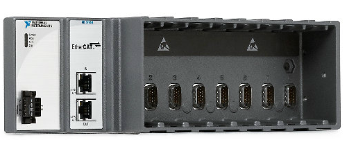
EtherCat expansion chassis: NI 9145
The NI 9145 is an 8-slot rugged EtherCAT slave chassis for adding deterministic, distributed I/O to NI EtherCAT master controllers. With standard CAT 5 Ethernet cabling, it communicates deterministically with any NI CompactRIO, real-time PXI, or real-time industrial controller that has two Ethernet ports. You can daisy chain multiple NI 9145 slave chassis from the master controller to expand time-critical applications to high-channel counts while maintaining hard determinism with minimal processor resources.
It also has a 2M gate Xilinx Spartan field-programmable gate array (FPGA), giving high-speed and customizable I/O timing, inline processing, and closed-loop control.
NI 9145 Technical details
General Data |
|
|---|---|
Number of slots |
8 |
Operating system |
Real-time |
Reconfigurable FPGA |
Spartan-3 |
Peripheral port |
|
EtherCAT |
|
Number of Ethernet ports |
2 |
Interface |
100BaseTx |
Communication rates |
100 Mb/s |
Max. cabling distance |
100 m/segment |
Environmental data |
|
Temperature IEC-60068-2-1 & IEC-60068-2-2 |
|
Operating temperature |
-40 – 70 ºC |
Storage temperature |
-40 – 85 ºC |
Humidity IEC-60068-2-56 |
|
Operating relative humidity |
10 – 90 %, non condensing |
Storage relative humidity |
5 – 95 %, non condensing |
Maximum altitude |
2000 m (800 mbar) |
Vibration IEC-60068-2-27 & IEC-60068-2-64 |
|
Operational shock |
30 g peak, 11 ms / 50 g, 3 ms |
Operating |
5 – 500 Hz, 5 g |
Non operating |
5 – 500 Hz, 5 g |
Electrical data |
|
Power |
20 W max. |
Rated voltage supply |
24 V DC |
Chassis input range |
9 to 30 V |
Mechanical data |
|
Dimensions |
|
Length |
284 mm |
Width |
881 mm |
Height |
589 mm |
Weight |
906 g |
Housing |
IP 40 |
Standards and Certifications |
|
Safety |
IEC 61010-1, EN 61010-1 UL 61010-1, CSA 61010-1 |
EMC |
EN 61326-1 (IEC 61326-1): Class A emissions; EN 55011 (CISPR 11): Group 1, Class A emissions AS/NZS CISPR 11: Group 1, Class A emissions FCC 47 CFR Part 15B: Class A emissions ICES-001: Class A emissions |
Hazardous locations |
Ex nA IIC T4 |
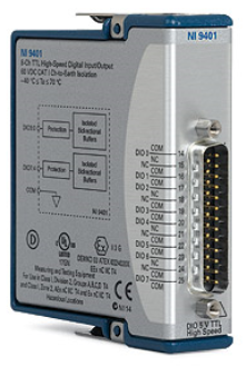
8 DIO Module: NI 9401
The NI 9401 is an 8-channel, 100 ns bidirectional digital input module for any NI CompactDAQ or CompactRIO chassis. It allows three configurations: eight digital inputs, eight digital outputs, or four digital inputs and four digital outputs.
Each channel is compatible with 5 V/TTL signals and features 1,000 Vrms transient isolation between the I/O channels and the backplane.
NI 9401 Technical details
General Data |
|
|---|---|
Product family |
Digital I/O |
Measurement type |
Digital Specialty digital |
Form factor |
CompactDAQ CompactRIO |
Isolation type |
Ch-Earth Ground Isolation |
Digital I/O |
|
Bidirectional channels |
8 |
Maximum clock rate |
10 MHz |
Timing |
Hardware |
Logic level |
TTL |
Max. I/O voltage |
0 – 5.25 V |
Environmental data |
|
Temperature IEC-60068-2-1 & IEC-60068-2-2 |
|
Operating temperature |
-40 – 70 ºC |
Storage temperature |
-40 – 85 ºC |
Humidity IEC-60068-2-56 |
|
Operating relative humidity |
10 – 90 %, non condensing |
Storage relative humidity |
5 – 95 %, non condensing |
Maximum altitude |
2000 m (800 mbar) |
Vibration IEC-60068-2-27 & IEC-60068-2-64 |
|
Operational shock |
30 g peak, 11 ms / 50 g, 3 ms |
Operating |
5 – 500 Hz, 5 g |
Non operating |
5 – 500 Hz, 5 g |
Electrical data |
|
Power |
|
Active mode |
580 mW max. |
Sleep mode |
1 mW max. |
Channel to COM max voltage |
± 30 V |
Channel – earth isolation |
60 V DC (continuous), 1000 Vrms (withstand) |
Mechanical data |
|
Dimensions |
|
Length |
90 mm |
Width |
23 mm |
Weight |
145 g |
Housing |
IP 40 |
Standards and Certifications |
|
Safety |
IEC 61010-1, EN 61010-1 UL 61010-1, CSA 61010-1 |
EMC |
EN 61326-1 (IEC 61326-1): Class A emissions; EN 55011 (CISPR 11): Group 1, Class A emissions AS/NZS CISPR 11: Group 1, Class A emissions FCC 47 CFR Part 15B: Class A emissions ICES-001: Class A emissions |
Hazardous locations |
Ex nA IIC T4 |
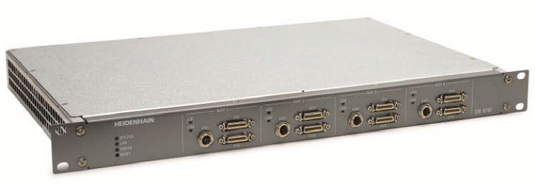
Encoder Heidenhain EIB 8791
EIB 8791 Technical details
General |
|---|
8 axes / system |
1Vss encoder signals |
Single and distance coded reference marks |
110-240V power supply |
Single height 19” unit |
Position Capture |
20 MHz input bandwidth |
Internal 50MHz position capture and calculation |
Selectable frequency filters |
48 Bit position output / 16 Bit Interpolation |
Various Output data types |
Position |
Speed |
Acceleration |
Position Corrections |
Enhanced online compensation of input signals |
Static compensation or high order signal deviation based on correction run |
Trigger Interface |
Versatile trigger interface |
Synchronous |
Asynchronous |
Common trigger or individual per axis |
Synchronization to master clock for sub-ns stable triggering |
Synchronization of several EIBs together (master-slave configuration) |
Position Output |
Fast position data link up to 10MSamples/s (per axis) |
UDP-interface |
Direct streaming (1 sample/packet) |
Batch streaming (up to 16 samples/packet) |
TCP-interface for transaction safe transfer |
Data recording |
Distributed I/O
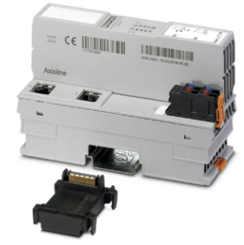
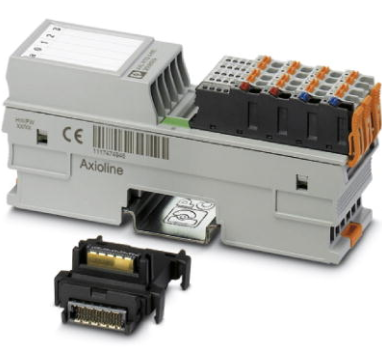
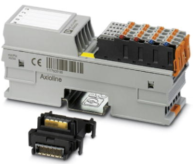
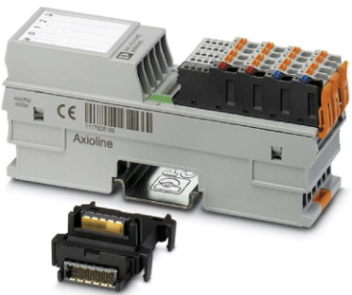
EtherCAT expansion chassis: Phoenix contact AXL F BK EC
The bus coupler represents the link between an EtherCAT® network and the Axioline F system.Up to 63 Axioline F devices can be connected to an existing EtherCAT® system using the bus coupler.
Phoenix contact AXL Technical details
Dimensions |
|
|---|---|
Width |
45 mm |
Height |
125.9 mm |
Depth |
74 mm |
Note on dimensions |
The depth is valid when a TH 35-7.5 DIN rail is used (according to EN 60715). |
Ambient conditions |
|
Ambient temperature (operation) |
-25 °C … 60 °C (Mounting position: wall mounting on horizontal DIN rail) |
-25 °C … 55 °C (Mounting position: any) |
|
Ambient temperature (storage/transport) |
-40 °C … 85 °C |
Permissible humidity (operation) |
5 % … 95 % (non-condensing) |
Permissible humidity (storage/transport) |
5 % … 95 % (non-condensing) |
Air pressure (operation) |
70 kPa … 106 kPa (up to 3000 m above sea level) |
Degree of protection |
IP20 |
Connection data |
|
Designation |
Axioline F connector |
Connection method |
Push-in connection |
Note on connection method |
Please observe the information provided on conductor cross sections in the “Axioline F: system and installation” user manual. |
Interfaces |
|
Fieldbus system |
Fernbus |
Designation |
EtherCAT® |
Connection method |
RJ45 socket, auto negotiation and auto crossing |
Transmission speed |
100 MBit/s (Full duplex) |
Transmission physics |
Ethernet in RJ45 twisted pair |
Fieldbus system |
Lokalbus |
Designation |
Axioline F local bus |
Connection method |
Bus base module |
Transmission speed |
100 MBit/s |
System limits of the bus coupler |
|
Amount of process data |
1024 Byte (for each data direction) |
Number of supported devices |
max. 63 (per station) |
Number of local bus devices that can be connected |
max. 63 |
Designation |
EtherCAT® |
System-specific protocols |
Mailbox protocols CAN application layer over EtherCAT® |
Mailbox protocols File access over EtherCAT® |
|
Type of addressing |
Auto-increment addressing |
Fixed position addressing |
|
Logical addressing |
|
Explicit device ID |
|
Power consumption |
|
Supply of communications power UL |
24 V DC |
Current consumption from UL |
typ. 105 mA (without I/Os and UL = 24 V) |
max. 570 mA (with 2 A at UBus for the I/Os and UL = 24 V) |
|
Communications power UBus |
5 V DC (via bus base module) |
Current supply at UBus |
2 A |
General & directives |
|
Net weight |
219.9 g |
Note on weight specifications |
with connector and bus base module |
Mounting type |
DIN rail |
Protection class |
III, IEC 61140, EN 61140, VDE 0140-1 |
Conformance with EMC directives |
Noise immunity test in accordance with EN 61000-6-2 Electrostatic discharge (ESD) EN 61000-4-2/IEC 61000-4-2 Criterion B; 6 kV contact discharge, 8 kV air discharge |
Noise immunity test in accordance with EN 61000-6-2 Electromagnetic fields EN 61000-4-3/IEC 61000-4-3 Criterion A; Field intensity: 10 V/m |
|
Noise immunity test in accordance with EN 61000-6-2 Fast transients (burst) EN 61000-4-4/IEC 61000-4-4 Criterion B, 2 kV |
|
Noise immunity test in accordance with EN 61000-6-2 Transient surge voltage (surge) EN 61000-4-5/IEC 61000-4-5 Criterion B; DC supply lines: ±0.5 kV/±0.5 kV (symmetrical/asymmetrical); fieldbus cable shield: ±1 kV |
|
Noise immunity test in accordance with EN 61000-6-2 Conducted interference EN 61000-4-6/IEC 61000-4-6 Criterion A; Test voltage 10 V |
|
Noise emission test according to EN 61000-6-3 Radio interference properties EN 55022 Class B |
|
Mechanical tests |
Vibration resistance in acc. with EN 60068-2-6/IEC 60068-2-6 5g |
Shock in acc. with EN 60068-2-27/IEC 60068-2-27 30g |
|
Continuous shock according to EN 60068-2-27/IEC 60068-2-27 10g |
|
Diagnostics messages |
Emergency messages |
Messages via object 10F3hex Diagnosis history |
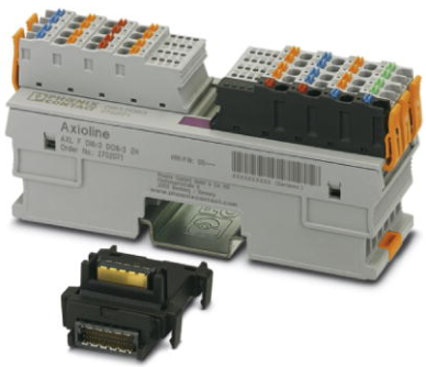
8DI/8DO module: Phoenix contact AXLF DIO8/3 DO8/3 2H
Axioline F digital input and output module, 8 inputs, 24 V DC, 8 outputs, 24 V DC, 500 mA, 2-, 3-conductor connection technology (including bus base module and connectors).
8DI/8DO module Technical details
Dimensions |
|
|---|---|
Width |
35 mm |
Height |
129.9 mm |
Depth |
54 mm |
Note on dimensions |
The depth is valid when a TH 35-7.5 DIN rail is used (according to EN 60715). |
Ambient conditions |
|
Ambient temperature (operation) |
-25 °C … 60 °C (Mounting position: wall mounting on horizontal DIN rail) |
-25 °C … 55 °C (Mounting position: any) |
|
Ambient temperature (storage/transport) |
-40 °C … 85 °C |
Permissible humidity (operation) |
5 % … 95 % (non-condensing) |
Permissible humidity (storage/transport) |
5 % … 95 % (non-condensing) |
Air pressure (operation) |
70 kPa … 106 kPa (up to 3000 m above sea level) |
Degree of protection |
IP20 |
Connection data |
|
Designation |
Axioline F connector |
Connection method |
Push-in connection |
Note on connection method |
Please observe the information provided on conductor cross sections in the “Axioline F: system and installation” user manual. |
Digital inputs |
|
Input name |
Digital inputs |
Description of the input |
EN 61131-2 types 1 and 3 |
Connection method |
Push-in connection |
2, 3-wire |
|
Number of inputs |
8 |
Protective circuit |
Polarity reversal protection of the inputs Electronic |
Input filter time |
3000 µs (default) |
Input voltage range “0” signal |
-3 V DC … 5 V DC |
Input voltage range “1” signal |
11 V DC … 30 V DC |
Nominal input current at UIN |
2.4 mA |
Digital outputs |
|
Output name |
Digital outputs |
Connection method |
Push-in connection |
2, 3-wire |
|
Number of outputs |
8 |
Protective circuit |
Short-circuit protection, overload protection of the outputs Electronic |
Output voltage |
24 V DC |
Nominal output voltage |
24 V DC |
Maximum output current per channel |
500 mA |
Maximum output current per module |
8 A (external fuse) |
Nominal load, inductive |
max. 12 VA (1.2 H; 48 Ω; with nominal voltage) |
Nominal load, lamp |
max. 12 W (at nominal voltage) |
Nominal load, ohmic |
max. 12 W (48 Ω; with nominal voltage) |
Interfaces |
|
Designation |
Axioline F local bus |
Connection method |
Bus base module |
Transmission speed |
100 MBit/s |
Power consumption |
|
Communications power UBus |
5 V DC (via bus base module) |
Current consumption from UBus |
max. 120 mA |
Digital input and output module supply UIO |
24 V DC |
Current consumption from UIO |
max. 6 A (external fuse) |
General & directives |
|
Net weight |
159 g |
Note on weight specifications |
with connectors and bus base module |
Mounting type |
DIN rail |
Protection class |
III, IEC 61140, EN 61140, VDE 0140-1 |
Test section |
5 V communications power (logic), 24 V supply (I/O) 500 V AC 50 Hz 1 min |
5 V supply (logic)/functional earth ground 500 V AC 50 Hz 1 min |
|
24 V supply (I/O) / functional earth ground 500 V AC 50 Hz 1 min |
|
Conformance with EMC directives |
Noise immunity test in accordance with EN 61000-6-2 Electrostatic discharge (ESD) EN 61000-4-2/IEC 61000-4-2 Criterion B; 6 kV contact discharge, 8 kV air discharge |
Noise immunity test in accordance with EN 61000-6-2 Electromagnetic fields EN 61000-4-3/IEC 61000-4-3 Criterion A; Field intensity: 10 V/m |
|
Noise immunity test in accordance with EN 61000-6-2 Fast transients (burst) EN 61000-4-4/IEC 61000-4-4 Criterion B, 2 kV |
|
Noise immunity test in accordance with EN 61000-6-2 Transient surge voltage (surge) EN 61000-4-5/IEC 61000-4-5 Criterion B; DC supply lines: ±0.5 kV/±0.5 kV (symmetrical/asymmetrical) |
|
Noise immunity test in accordance with EN 61000-6-2 Conducted interference EN 61000-4-6/IEC 61000-4-6 Criterion A; Test voltage 10 V |
|
Noise emission test according to EN 61000-6-3 Radio interference properties EN 55022 Class B |
|
Mechanical tests |
Vibration resistance in acc. with EN 60068-2-6/IEC 60068-2-6 5g |
Shock in acc. with EN 60068-2-27/IEC 60068-2-27 30g |
|
Continuous shock according to EN 60068-2-27/IEC 60068-2-27 10g |
|
Diagnostics messages |
I/O supply failure Yes |
Short-circuit / overload of the digital outputs Yes |
4RTD module: Phoenix contact AXLF RTD4 1H
Axioline F temperature module, 4 inputs for connecting resistance temperature detectors.
AXLF RTD4 1H Technical details
Dimensions |
|
|---|---|
Width |
35 mm |
Height |
126.1 mm |
Depth |
54 mm |
Note on dimensions |
The depth is valid when a TH 35-7.5 DIN rail is used (according to EN 60715). |
Ambient conditions |
|
Ambient temperature (operation) |
-25 °C … 60 °C (Mounting position: wall mounting on horizontal DIN rail) |
-25 °C … 55 °C (Mounting position: any) |
|
Ambient temperature (storage/transport) |
-40 °C … 85 °C |
Permissible humidity (operation) |
5 % … 95 % (non-condensing) |
Permissible humidity (storage/transport) |
5 % … 95 % (non-condensing) |
Air pressure (operation) |
70 kPa … 106 kPa (up to 3000 m above sea level) |
Degree of protection |
IP20 |
Connection data |
|
Designation |
Axioline F connector |
Connection method |
Push-in connection |
Note on connection method |
Please observe the information provided on conductor cross sections in the “Axioline F: system and installation” user manual. |
Analog inputs |
|
Number of inputs |
4 (for resistance temperature detectors) |
Input name |
Analog inputs |
Description of the input |
Inputs for resistive temperature sensors |
Connection method |
Spring-cage connection with direct connector-in method |
2, 3, 4-wire (shielded) |
|
Sensor types (RTD) that can be used |
Pt, Ni, KTY, Cu sensors |
Linear resistance measuring range |
0 Ω … 500 Ω |
0 kΩ … 5 kΩ |
|
Nominal value of the current sources |
1 mA (Pt 100, Ni 100, RLin 500 Ω; pulse current, the specification is valid during the sampling phase) |
Measured value representation |
16 bits (15 bits + sign bit) |
Resolution A/D |
24 bit |
Protective circuit |
Short-circuit protection, overload protection of the inputs |
Data formats |
IB IL, S7-compatible |
Precision |
See Tables under tolerance values |
Input filter time |
40 ms |
Interfaces |
|
Designation |
Axioline F local bus |
Connection method |
Bus base module |
Transmission speed |
100 MBit/s |
Power consumption |
|
Communications power UBus |
5 V DC (via bus base module) |
Current consumption from UBus |
max. 140 mA |
Supply for analog modules UA |
24 V DC |
Current consumption from UA |
max. 17 mA |
General & directives |
|
Net weight |
144 g |
Note on weight specifications |
with connectors and bus base module |
Mounting type |
DIN rail |
Protection class |
III, IEC 61140, EN 61140, VDE 0140-1 |
Test section |
5 V communications power (logic), 24 V supply (I/O) 500 V AC 50 Hz 1 min |
5 V supply (logic)/functional earth ground 500 V AC 50 Hz 1 min |
|
24 V supply (I/O) / functional earth ground 500 V AC 50 Hz 1 min |
|
Conformance with EMC directives |
Noise immunity test in accordance with EN 61000-6-2 Electrostatic discharge (ESD) EN 61000-4-2/IEC 61000-4-2 Criterion B; 6 kV contact discharge, 8 kV air discharge |
Noise immunity test in accordance with EN 61000-6-2 Electromagnetic fields EN 61000-4-3/IEC 61000-4-3 Criterion A; Field intensity: 10 V/m |
|
Noise immunity test in accordance with EN 61000-6-2 Fast transients (burst) EN 61000-4-4/IEC 61000-4-4 Criterion B, 2 kV |
|
Noise immunity test in accordance with EN 61000-6-2 Transient surge voltage (surge) EN 61000-4-5/IEC 61000-4-5 Criterion B; supply lines DC: ±0.5 kV/±0.5 kV (symmetrical/asymmetrical); ±1 kV to shielded I/O cables |
|
Noise immunity test in accordance with EN 61000-6-2 Conducted interference EN 61000-4-6/IEC 61000-4-6 Criterion A; Test voltage 10 V |
|
Noise emission test according to EN 61000-6-3 Radio interference properties EN 55022 Class B |
|
Mechanical tests |
Vibration resistance in acc. with EN 60068-2-6/IEC 60068-2-6 5g |
Shock in acc. with EN 60068-2-27/IEC 60068-2-27 25g, 11 ms period, half-sine shock pulse |
|
Continuous shock according to EN 60068-2-27/IEC 60068-2-27 10g |
4AO module: Phoenix contact AXLF AO4 1H
Axioline F analog output module, 4 outputs: 0 - 10 V, ±10 V, 0 - 5 V, ±5 V, 0 - 20 mA, 4 - 20 mA, 2-wire connection technology (including bus base module and connectors).
Phoenix contact AXLF AO4 1H Technical details
Dimensions |
|
|---|---|
Width |
35 mm |
Height |
126.1 mm |
Depth |
54 mm |
Note on dimensions |
The depth is valid when a TH 35-7.5 DIN rail is used (according to EN 60715). |
Ambient conditions |
|
Ambient temperature (operation) |
-25 °C … 60 °C (Mounting position: wall mounting on horizontal DIN rail) |
-25 °C … 55 °C (Mounting position: any) |
|
Ambient temperature (storage/transport) |
-40 °C … 85 °C |
Permissible humidity (operation) |
5 % … 95 % (non-condensing) |
Permissible humidity (storage/transport) |
5 % … 95 % (non-condensing) |
Air pressure (operation) |
70 kPa … 106 kPa (up to 3000 m above sea level) |
Degree of protection |
IP20 |
Connection data |
|
Designation |
Axioline F connector |
Connection method |
Push-in connection |
Note on connection method |
Please observe the information provided on conductor cross sections in the “Axioline F: system and installation” user manual. |
Analog outputs |
|
Number of outputs |
4 |
Connection method |
Push-in connection |
2-wire (shielded, twisted pair) |
|
Output name |
Analog outputs |
D/A resolution |
16 bit |
Type of protection |
Short-circuit and overload protection |
Transient protection |
Protective circuit/component |
Electronic |
Suppressor diode |
Data formats |
IB IL, S7-compatible |
Representation of output values |
16 bits (15 bits + sign) |
Process data update |
140 µs |
Current output signal |
0 mA … 20 mA |
4 mA … 20 mA |
|
Load/output load current output |
≤ 500 Ω |
Voltage output signal |
0 V … 5 V |
-5 V … 5 V |
|
0 V … 10 V |
|
-10 V … 10 V |
|
Load/output load voltage output |
> 1 kΩ |
Precision |
typ. 0.1 % (of output range final value) |
typ. 0.1 % (of output range final value) |
|
Interfaces |
|
Designation |
Axioline F local bus |
Connection method |
Bus base module |
Transmission speed |
100 MBit/s |
Power consumption |
|
Communications power UBus |
5 V DC (via bus base module) |
Current consumption from UBus |
typ. 120 mA |
max. 150 mA |
|
Supply for analog modules UA |
24 V DC |
Current consumption from UA |
typ. 40 mA (induced current consumption; no load, 0 V output) |
typ. 60 mA (4 voltage channels, 10 V output) |
|
max. 110 mA (4 current channels, 20 mA output, 500 Ω load) |
|
General & directives |
|
Net weight |
145 g |
Note on weight specifications |
with connectors and bus base module |
Mounting type |
DIN rail |
Protection class |
III, IEC 61140, EN 61140, VDE 0140-1 |
Test section |
5 V communications power (logic), 24 V supply (I/O) 500 V AC 50 Hz 1 min |
5 V supply (logic)/analog outputs 500 V AC 50 Hz 1 min |
|
5 V supply (logic)/functional earth ground 500 V AC 50 Hz 1 min |
|
24 V supply (I/O)/analog outputs 500 V AC 50 Hz 1 min |
|
24 V supply (I/O) / functional earth ground 500 V AC 50 Hz 1 min |
|
Analog outputs/functional earth ground 500 V AC 50 Hz 1 min |
|
Conformance with EMC directives |
Noise immunity test in accordance with EN 61000-6-2 Electrostatic discharge (ESD) EN 61000-4-2/IEC 61000-4-2 Criterion B; 6 kV contact discharge, 8 kV air discharge |
Noise immunity test in accordance with EN 61000-6-2 Electromagnetic fields EN 61000-4-3/IEC 61000-4-3 Criterion A; Field intensity: 10 V/m |
|
Noise immunity test in accordance with EN 61000-6-2 Fast transients (burst) EN 61000-4-4/IEC 61000-4-4 Criterion B, 2 kV |
|
Noise immunity test in accordance with EN 61000-6-2 Transient surge voltage (surge) EN 61000-4-5/IEC 61000-4-5 Criterion B; supply lines DC: ±0.5 kV/±0.5 kV (symmetrical/asymmetrical); ±1 kV to shielded I/O cables |
|
Noise immunity test in accordance with EN 61000-6-2 Conducted interference EN 61000-4-6/IEC 61000-4-6 Criterion A; Test voltage 10 V |
|
Noise emission test according to EN 61000-6-3 Radio interference properties EN 55022 Class B |
|
Mechanical tests |
Vibration resistance in acc. with EN 60068-2-6/IEC 60068-2-6 5g |
Shock in acc. with EN 60068-2-27/IEC 60068-2-27 30g |
|
Continuous shock according to EN 60068-2-27/IEC 60068-2-27 10g |
4AI Module: Phoenix contact AXLF AI4 I 1H
Axioline F analog input module, 4 inputs: 0 - 20 mA, 4 - 20 mA, ±20 mA, 2, 3, and 4-conductor connection technology, integrated sensor supply (including bus base module and connectors)
Phoenix contact AXLF AI4 I 1H Technical details
Dimensions |
|
|---|---|
Width |
35 mm |
Height |
126.1 mm |
Depth |
54 mm |
Note on dimensions |
The depth is valid when a TH 35-7.5 DIN rail is used (according to EN 60715). |
Ambient conditions |
|
Ambient temperature (operation) |
-25 °C … 60 °C |
-25 °C … 55 °C |
|
Ambient temperature (storage/transport) |
-40 °C … 85 °C |
Permissible humidity (operation) |
5 % … 95 % (non-condensing) |
Permissible humidity (storage/transport) |
5 % … 95 % (non-condensing) |
Air pressure (operation) |
70 kPa … 106 kPa (up to 3000 m above sea level) |
Degree of protection |
IP20 |
Connection data |
|
Designation |
Axioline F connector |
Connection method |
Push-in connection |
Note on connection method |
Please observe the information provided on conductor cross sections in the “Axioline F: system and installation” user manual. |
Analog inputs |
|
Number of inputs |
4 (Differential inputs, current) |
Connection method |
Push-in connection |
2, 3, 4-wire (shielded) |
|
Input name |
Analog inputs |
A/D conversion time |
31.25 µs |
Resolution A/D |
16 bit |
Limit frequency (3 dB) |
30 Hz |
12 kHz |
|
Type of protection |
Transient protection of inputs |
Protective circuit/component |
Suppressor diode |
Data formats |
IB IL, S7-compatible |
Measured value representation |
16 bits (15 bits + sign bit) |
Current input signal |
0 mA … 20 mA |
4 mA … 20 mA |
|
-20 mA … 20 mA |
|
Precision |
0.1 % (of measuring range final value for active mean-value generation and 30 Hz filter) |
Input filter |
30 Hz, 12 kHz and mean-value generation (can be parameterized) |
Number of inputs |
4 (Differential inputs, current) |
Type of protection |
Overload protection |
Protective circuit/component |
No; ±5.2 V DC, maximum, Imax = 50 mA |
Open circuit response |
Going to 0 mA; open-circuit detection from 4 mA … 20 mA |
Interfaces |
|
Designation |
Axioline F local bus |
Connection method |
Bus base module |
Transmission speed |
100 MBit/s |
Power consumption |
|
Communications power UBus |
5 V DC (via bus base module) |
Current consumption from UBus |
typ. 120 mA |
max. 150 mA |
|
Supply for analog modules UA |
24 V DC (I/O supply and sensor supply) |
Current consumption from UA |
typ. 38 mA (IiS = 0 mA) |
max. 45 mA (IiS = 0 mA) |
|
typ. 118 mA (IiS = 4 x 20 mA (nominal load)) |
|
max. 125 mA (IiS = 4 x 20 mA (nominal load)) |
|
typ. 238 mA (IiS = 4 x 50 mA (full load)) |
|
max. 245 mA (IiS = 4 x 50 mA (full load)) |
|
General & directives |
|
Net weight |
145 g |
Note on weight specifications |
with connectors and bus base module |
Mounting type |
DIN rail |
Protection class |
III, IEC 61140, EN 61140, VDE 0140-1 |
Test section |
5 V communications power (logic), 24 V supply (I/O) 500 V AC 50 Hz 1 min |
5 V supply (logic)/analog outputs 500 V AC 50 Hz 1 min |
|
5 V supply (logic)/functional earth ground 500 V AC 50 Hz 1 min |
|
24 V supply (I/O)/analog outputs 500 V AC 50 Hz 1 min |
|
24 V supply (I/O) / functional earth ground 500 V AC 50 Hz 1 min |
|
Analog outputs/functional earth ground 500 V AC 50 Hz 1 min |
|
Conformance with EMC directives |
Noise immunity test in accordance with EN 61000-6-2 Electrostatic discharge (ESD) EN 61000-4-2/IEC 61000-4-2 Criterion B; 6 kV contact discharge, 8 kV air discharge |
Noise immunity test in accordance with EN 61000-6-2 Electromagnetic fields EN 61000-4-3/IEC 61000-4-3 Criterion A; Field intensity: 10 V/m |
|
Noise immunity test in accordance with EN 61000-6-2 Fast transients (burst) EN 61000-4-4/IEC 61000-4-4 Criterion B, 2 kV |
|
Noise immunity test in accordance with EN 61000-6-2 Transient surge voltage (surge) EN 61000-4-5/IEC 61000-4-5 Criterion B; supply lines DC: ±0.5 kV/±0.5 kV (symmetrical/asymmetrical); ±1 kV to shielded I/O cables |
|
Noise immunity test in accordance with EN 61000-6-2 Conducted interference EN 61000-4-6/IEC 61000-4-6 Criterion A; Test voltage 10 V |
|
Noise emission test according to EN 61000-6-3 Radio interference properties EN 55022 Class B |
|
Mechanical tests |
Vibration resistance in acc. with EN 60068-2-6/IEC 60068-2-6 5g |
Shock in acc. with EN 60068-2-27/IEC 60068-2-27 30g |
|
Continuous shock according to EN 60068-2-27/IEC 60068-2-27 10g |
Drives
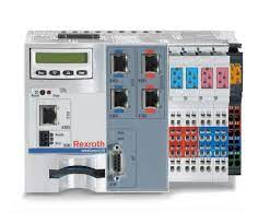
Controller: Bosch-Rexroth IndraMotion MLC L75
IndraMotion MLC is the first truly complete automation system. It combines motion control, robot control and logic control to create a uniform complete system for any control task in almost any industry.
IndraMotion MLC L75 Technical details
Platform |
L75 |
|---|---|
Drive interface |
Sercos III |
Max. axis number |
64 |
Cycle time |
0.5/0.25 ms |
Max. number of function modules |
4 |
Onboard IO |
8I/8O |
C2C |
FM Sercos III |
Ethernet/IP Scanner/Adapter |
YES/YES |
PROFINET IO Contr./Device |
YES/YES |
PROFIBUS Master/Slave |
YES/YES |
Robot Control |
YES |
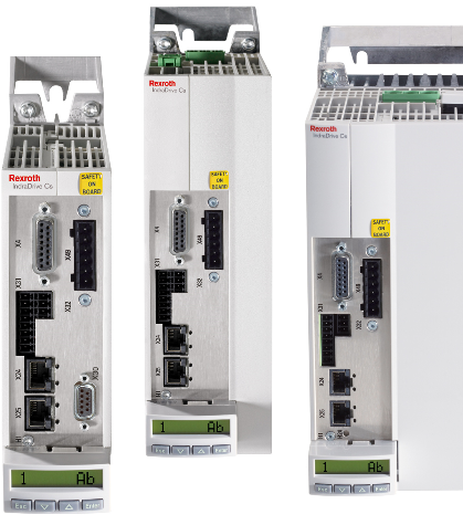
Drive: Bosch-Rexroth IndraDrive Cs
The IndraDrive C HCS01.15-W0028-A-03-B-ET-EC-NN-L3 will be used in the azimuth cable wrap. The second ones HCS01.E-W0008-A-03-B-ET-EC-NN-L3-NN-FW are the drives for the camera cable wrap.
Bosch-Rexroth IndraDrive Cs Technical details
Connectivity |
HCS01.15-W0028-A-03-B-ET-EC-NN-L3 |
HCS01.E-W0008-A-03-B-ET-EC-NN-L3-NN-FW |
|---|---|---|
Possible communication via |
SERCOS III PROFINET IO EtherNet/IP EtherCAT |
|
Performance data |
||
Continuous current |
11.52 A |
2.7 A |
Maximum current |
28 A |
8 A |
Mains connection voltage |
3 x AC 200… 500 V (10% tolerance) |
3 x AC 200… 500 V (10% tolerance) |
Frequency |
50… 60 Hz (2 Hz tolerance) |
50… 60 Hz (2 Hz tolerance) |
Continuous current main input |
10 A |
2.5 A |
Power dependency from the supply voltage |
||
1% power reduction per 4 V |
1% power reduction per 4 V |
|
No power increase |
No power increase |
|
Intermediate circuit |
||
Continuous power with choke |
4 kW |
- |
Max. power with choke |
9.7 kW |
- |
Continuous power without choke |
2.6 kW |
0.86 kW |
Max. power without choke |
6.2 kW |
2.58 kW |
Switching f/max. output f |
||
4 kHz |
0…400 Hz |
0…400 Hz |
8 kHz |
0…800 Hz |
0…800 Hz |
12 kHz |
0…1200 Hz |
0…1200 Hz |
16 kHz |
0…1600 Hz |
0…1600 Hz |
Output voltage |
3 x AC 0 … 500 V |
|
Intermediate circuit capacity |
0.39 mF |
0.11 mF |
Intermediate circuit voltage |
Mains connection voltage x 1.41 V DC |
|
Brake chopper/resistor |
||
Braking energy consumption |
3 kW |
0.8 kW |
Continuous braking power |
0.15 kW |
0.03 kW |
Maximum braking power |
10.6 kW |
4 kW |
Control voltage |
||
Control voltage |
24 V DC (5% tolerance) |
24 V DC (5% tolerance) |
Power consumption without control unit and motor brake |
34 W |
28 W |
Protection |
||
Protection category-overall |
IP20 |
IP20 |
OverVoltage category |
III |
III |
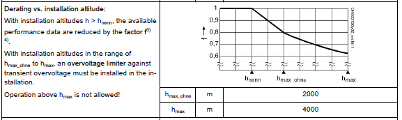
Environmental data |
||
Ambient temperature range for operation with nominal data |
0…40 ºC |
0…40 ºC |
Installation altitude |
1000 m |
1000 m |
Relative humidity |
5 … 95 % |
5 … 95 % |
Conductive dirt contamination |
Not allowed |
Not allowed |
Allowed pollution degree |
2 |
2 |
Allowed dust, steam |
EN 50178 tab. A.2 |
EN 50178 tab. A.2 |
Vibration sine: amplitude at 5 … 32 Hz |
0.6 mm 15% |
0.6 mm 15% |
Vibration sine: acceleration at 32…200 Hz |
1.3 g 15% |
1.3 g 15% |
Vibration noise (random) frequency |
20…500 |
20…500 |
Mechanical data |
||
Mass |
1.7 kg |
0.72 kg |
Dimensions |
||
Length T |
268 mm |
215 mm |
Width B |
70 mm |
50 mm |
Height H |
196 mm |
196 mm |
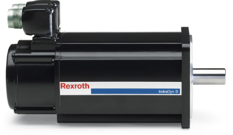
Servomotor: Bosch-Rexroth MSK070C-0300 & MSK040B-0450
Servomotor.
Bosch-Rexroth MSK drives Technical details
Performance data |
MSK070C-0300 |
MSK040B-0450 |
|---|---|---|
Continuous torque at standstill, |
||
13 Nm |
1.7 Nm |
|
14.5 Nm |
- |
|
Surface |
19.5 Nm |
- |
Continuous current at standstill, |
||
8.2 A |
2.0 A |
|
9.2 A |
- |
|
Surface |
12.3 A |
- |
Maximum torque |
33 Nm |
5.1 Nm |
Maximum current |
32.8 A |
8 A |
Torque constant @ 20 ºC |
1.74 Nm/A |
0.95 Nm/A |
Constant voltage @ 20 ºC |
107 V/min |
58.5 V/min |
Winding resistance @ 20 ºC |
1.13 Ohms |
7.9 Ohms |
Winding inductivity |
8.3 mH |
36 mH |
Leakage capacitance |
4 nF |
1.5 nF |
Number of pole pairs |
6 |
4 |
Moment of inertia of rotor without brake |
0.00291 kg m2 |
0.0001 |
Thermal time constant |
22 min |
13 min |
Maximum speed |
5500 rpm |
7500 rpm |
Sound pressure level |
< 75 dB |
< 75 dB |
Environmental data |
||
Ambient temperature during operation |
0…40ºC, if > 40ºC, power derating (look factor) |
0…40ºC, if > 40ºC, power derating (look factor) |
Setup elevation |
0…1000ºC, if > 1000 m, power derating |
0…1000ºC, if > 1000 m, power derating |
Relative humidity |
5 … 95 % |
5 … 95 % |
Mechanical data |
||
Degree of protection |
IP65 |
IP65 |
Insulation class (EN 60034-1) |
F |
F |
Dimensions |
||
Length |
238 mm |
155.5 mm |
Height |
202 mm |
124.5 mm |
Width |
140 mm |
82 mm |
Mass |
16.2 kg |
3.6 kg |
Holding brake data |
||
Holding torque |
23 Nm |
4 Nm |
Rated voltage (10%) |
24 V |
24 V |
Rated current |
0.79 A |
0.5 A |
Connection time |
130 ms |
35 ms |
Disconnection time |
180 ms |
25 ms |
Moment of inertia brake |
0.0003 kg m2 |
0.000023 kg m2 |
Mass brake |
1. 6 kg |
0.3 kg |
Standards |
|---|
98/37/EG, 89/336/EEC, DIN EN 50178; VDE0160, DIN IEC 60364-4-41;VDE 0100 part 410, DIN 332-2, DIN 6885-1, DIN EN 60034-1; VDE0530 Part 1, DIN VDE 0298-4; VDE 0298 Part 4, DIN EN 60204-1; VDE, 0113 Part 1, DIN 42955, DIN 748-1, DIN EN 60034-14; VDE 0530 Part 14, IEC 721-3-3 replaced, by DIN EN 60721-3-3, IEC 721-1 replaced by DIN IEC 60721-1, DIN EN 60529; VDE 0470 Part 1, DIN EN 60034-7; VDE 0530 Part 7, DIN 3760, DIN ISO 281. |

Power supply: Bosch-Rexroth KCU02.1N-ET-ET
Power supply for Bosch-Rexroth drives and servomotors.
Bosch Rexroth KCU02.1N-ET-ET power supply Technical details
Bosch Rexroth KCU02.1N-ET-ET |
|
|---|---|
Power section data |
|
Power dissipation at continuous current and continuous DC bus power respectively |
90 W |
Insulation resistance at DC 500 V |
> 50 MOhms |
Data control voltage - Input |
|
Control voltage |
24 V 20% |
Rated power consumption control voltage input |
675 W |
Maximum inrush current @ 24 VDC supply |
8 A (< 1 s) |
Input capacitance |
11 mF |
Maximum allowed voltage for 1 ms |
33 V |
Data control voltage - Output |
|
Nominal voltage |
42 V |
Nominal power |
588 W |
Data power section - Input |
|
Rated input voltage |
540 … 750 V DC |
Rated input current |
25 A |
Capacitance in DC bus |
< 0.0001 mF |
Capacitance against housing |
2 x 100 nF |
Maximum allowed voltage for 1 ms |
33 V |
Short circuit current rating |
42000 Arms |
Data power section – Output |
|
Output voltage |
540 … 750 V DC |
Output current |
25 A |
Rated power (t > 10 min & fs = 4 kHz) |
14.0 … 18.8 kW |
Maximum allowed DC bus power |
42.0 … 53.3 kW |
Protection |
|
Protection category-overall |
IP20 |
OverVoltage category |
III (IEC60664-1) |
Mechanical data |
|
Mass |
3.8 kg |
Dimensions |
|
Depth D |
252 mm |
Width B |
50 mm |
Height H |
378 mm |
Minimum distance on the top |
80 mm |
Minimum distance on the bottom |
110 mm |
Horizontal spacing |
0 mm |
Cooling |
|
Type |
Forced |
Volumetric capacity of forced cooling |
0.3 m3/h (approx.) |
Environmental data |
|
Ambient temperature range for operation with nominal data |
0…40 ºC |
Installation altitude |
1000 m |
Relative humidity |
5 … 95 % |
Conductive dirt contamination |
Not allowed |
Allowed pollution degree |
2 |
Allowed dust, steam |
EN 50178 tab. A.2 |
Vibration sine: amplitude at 5 … 32 Hz |
0.6 mm 15% |
Vibration sine: acceleration at 32…200 Hz |
1.3 g 15% |
Vibration noise (random) frequency |
20…500 |
Average sound pressure level |
< 70 dB |
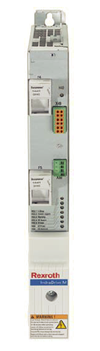
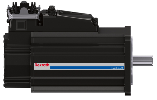
Motor-integrated drive: Bosch-Rexroth KSM02.1B-041C-42N-M3-HP2-ET-NN-D7-NN-TW
Motor integrated drive.
Bosch-Rexroth KSM02.1B-041C-42N-M3-HP2-ET-NN-D7-NN-TW drive Technical details
General data |
|
|---|---|
Safe torque off |
|
Multi-Ethernet Communication |
Sercos |
Profinet |
|
Ethernet/IP |
|
EtherCAT |
|
Data power section |
|
Rated power (t > 10 min) |
470 W |
Power dissipation at continuous current and continuous DC bus power respectively |
70 W |
Rated input voltage, power |
540…750 V |
Capacitance in DC bus |
0.012 mF |
Capacitance against housing |
- |
Allowed switching frequencies |
4-8 kHz |
Data motor stage |
|
Continuous torque at standstill, 60 K |
2.2 Nm |
Maximum torque |
9.4 Nm |
Maximum current |
6.8 A |
Torque constant @ 20ºC |
1.6 Nm/A |
Constant voltage @ 20ºC |
98.2 V/1000min |
Rotor inertia |
0.00019 kg m2 |
Thermal time constant |
13 min |
Maximum speed |
5500 rpm |
Thermal class according to EN 600034-1 |
155 |
Holding brake |
|
Holding torque |
4 Nm |
Clamping delay |
25 ms |
Release delay |
35 ms |
Mass brake |
- |
Inertia brake |
0.000023 kg m2 |
Environmental data |
|
Ambient temperature range for operation with nominal data |
0…40 ºC (Note 1) |
Relative humidity |
5 … 95 % |
Average sound pressure level |
<75 dB |
Control voltage |
|
Control voltage |
20.4…28.8 V |
Maximum allowed over-voltage |
33 V (1 ms) |
Rated power consumption control voltage |
29.5 W |
Protection |
|
Protection category-overall |
IP65 |
Ambient conditions according to UL50/50E |
Type 4X Indoor use only |
Mechanical data |
|
Mass |
5.9 kg |
Dimensions |
|
Length T |
252 mm |
Width B |
82 mm |
Height H |
194 mm |
It has consulted Bosch Rexroth and they have confirmed that no problem working from -15ºC to 40°C.
Cabinet Cooling/Heating system
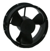
Fan cooler: Lytron Ostro fan
Cooling fan.
Lytron Ostro fan Technical details
Performance data |
|
|---|---|
Speed |
1400 rpm |
Max air flow |
13 m3/min |
Max pressure |
8 mm H2O |
Noise |
52 dB |
Environmental data |
|
Operating temperature |
-40 – 70 ºC |
Electrical data |
|
Rated voltage |
230 Vac |
Frequency |
50 Hz |
Input power |
31 W |
Rated current |
0.14 Arms |
Locked current |
0.26 Arms |
Motor |
|
Capacitor start |
Yes |
Insulation class |
B |
Thermal protected |
Yes |
Dielectric strength |
AC 1500 V, one min. |
Mechanical data |
|
Dimensions |
10.0 dia x 3.5 inches (254 dia x 89 mm) |
Weight |
1.9 kg |
Bearings |
Balls |
Construction |
Frame: Aluminum Impeller: PBT |
Life expectancy |
|
Continuous duty |
50000 hours |
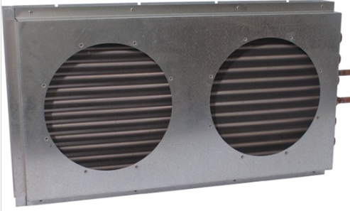
Heat exchanger: Lytron M14-240
Copper oem coil tube-fin heat exchanger
Lytron M14-240 heat exchanger Technical details
Mechanical data |
|
|---|---|
Dimensions |
|
Width |
711 mm |
Height |
51 mm |
Length |
356 mm |
Weight |
8.39 kg |
Type |
Tube-Fin Liquid-to-Air |
Fin material |
Aluminum |
Wetted path |
Copper |
Fan plate |
Included |
Fluid data |
|
Compatibility |
Water, Common coolants |
Fluid volume |
1090 ml |
Max. pressure |
10 bar |
Max.flow rate |
15.1 l.p.m |
Liquid pressure drop |
0.9 bar |
Air pressure drop |
29.89 Pa |
Thermal data |
|
Continuous thermal output |
4600 W |
Max. temperature |
200 ºC |
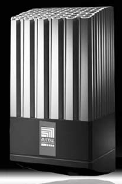
Heater: Rittal SK3105.380
This is the heater for the main electrical cabinet.
SK3105.380 panel heater Technical details
Mechanical data |
SK3105.380 |
|
|---|---|---|
Dimensions |
||
Width |
103 mm |
|
Height |
200 mm |
|
Depth |
103 mm |
|
Hole distance |
171 mm |
|
Electrical data |
||
Rated voltage |
110 – 240 V AC |
|
Rated frequency |
50 - 60 Hz |
|
230 V gG prefusible |
4 A @ 230 V AC |
|
Thermal data |
||
Continuous thermal output |
250 @ Tu = 10ºC |
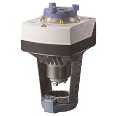
Mixing valve Siemens SAX61.03
The mixing valves used in the MCS.
Siemens SAX61.03 Technical details
Technical Specification |
|
|---|---|
Fail Safe |
No |
Positioning signal |
DC 0…10 V, DC 4…20 mA, 0…1000 Ohm |
Position feedback |
DC 0…10 V |
Power consumption |
8 VA |
Mounting position |
Nema 1 (interior only), Upright to horizontal |
Ambient humidity, operation |
95 % r.h. |
Operating voltage |
24 VAC/DC |
Supply Voltage |
24 VAC |
Frequency |
50/60 |
Stroke |
20 mm |
Positioning time |
30 s |
Stroke, mm |
20 mm |
Ambient temperature, operation |
-5…55 °C |
Dimensions (W x H x D) |
4.88 x 9.53 x 5.91 in |
Degree of protection |
IP54 |
Spring return function |
Non-spring return functionality |
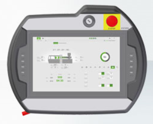
Hand Held Device HHD: Keba KeTop T200
Mobile terminal with HD-ready display.
KeTop T200 HMI Technical details
Display data |
|
|---|---|
Size |
10’ |
Resolution |
WXGA, 1280 x 800 |
Touch screen |
Analog resistive |
Operation elements |
|
Selection switch |
2, 4 or 16 positions |
Key switch |
Yes |
Push buttons |
Yes |
Membrane keyboard |
36 tactile keys front side 12 tactile keys read side |
Safety elements |
|
Switch |
3-level enabling switch |
Emergency stop button |
Yes |
Safety category |
PLe, En 13849-1 & SIL3, EN 61508 |
Hardware data |
|
Processor |
Intel Atom E3815 |
Memory |
32 GB Flash, 4 GB RAM |
Communication |
Ethernet 10/100 Mb/s |
Data back-up |
USB 2.0 |
Environmental data |
|
Temperature |
|
Operating temperature |
0 – 45 ºC |
Storage temperature |
-25 – 70 ºC |
Relative humidity |
5-95%, non-condensing |
Vibration/Shock resistance |
EN 61131-2 |
EMC immunity/emission |
Directive 2004/108/EG |
Electrical data |
|
Voltage supply |
24 V DC |
Max. power |
15 W |
Max. current |
400 mA @ 24 V |
Mechanical data |
|
Dimensions |
|
Width |
275 mm |
Height |
110 mm |
Length |
350 mm |
Weight |
1850 g |
Housing |
ABS-PC, IP 65 |
Standards and Certifications |
|
Approvals |
UL, SIBE |
Power supply unit: Phoenix contact QUINT PS/3AC/24DC/20
Power supply for DIN rail mounting. 3 phase voltage input to 24 V DC/20 A.
Phoenix contact QUINT PS/3AC/24DC/20
Phoenix contact QUINT PS/3AC/24DC/20 Technical details
Dimensions |
|
|---|---|
Width |
60 mm |
Height |
130 mm |
Depth |
125 mm |
Width with alternative assembly |
122 mm |
Height with alternative assembly |
130 mm |
Depth with alternative assembly |
63 mm |
Ambient conditions |
|
Degree of protection |
IP20 |
Ambient temperature (operation) |
-25 °C … 70 °C (> 60 °C Derating: 2,5 %/K) |
Ambient temperature (storage/transport) |
-40 °C … 85 °C |
Max. permissible relative humidity (operation) |
≤ 95 % (at 25 °C, non-condensing) |
Noise immunity |
EN 61000-6-2:2005 |
Maximum altitude |
5000 m |
Input data |
|
Nominal input voltage range |
3x 400 V AC … 500 V AC |
Input voltage range |
3x 320 V AC … 575 V AC |
2x 360 V AC … 575 V AC |
|
450 V DC … 800 V DC |
|
AC frequency range |
45 Hz … 65 Hz |
Frequency range DC |
0 Hz |
Discharge current to PE |
< 3.5 mA |
Inrush surge current |
< 20 A (typical) |
Power failure bypass |
> 28 ms (400 V AC) |
> 43 ms (500 V AC) |
|
Choice of suitable circuit breakers |
6 A … 16 A (AC: Characteristics B, C, D, K) |
Type of protection |
Transient surge protection |
Protective circuit/component |
Varistor, gas-filled surge arrester |
Output data |
|
Nominal output voltage |
24 V DC ±1 % |
Setting range of the output voltage |
18 V DC … 29.5 V DC (> 24 V DC, constant capacity restricted) |
Nominal output current |
20 A (-25°C … 60°C, UOUT = 24 V DC) |
POWER BOOST |
26 A (-25°C … 40°C permanent, UOUT = 24 V DC ) |
SFB technology current reserve |
120A (12 ms) |
Derating |
60 °C … 70 °C (2.5%/K) |
Connection in parallel |
Yes, for redundancy and increased capacity |
Connection in series |
Yes |
Control deviation |
< 1 % (change in load, static 10 % … 90 %) |
< 3 % (change in load, dynamic 10 % … 90 %) |
|
< 0.1 % (change in input voltage ±10 %) |
|
Residual ripple |
< 20 mVPP (with nominal values) |
Output power |
480 W |
Typical response time |
< 0.16 s |
Peak switching voltages nominal load |
< 40 mVPP (at nominal values, 20 MHz) |
Maximum power dissipation in no-load condition |
11 W |
Power loss nominal load max. |
40W |
General & directives |
|
Net weight |
1.5 kg |
Operating voltage display |
Green LED |
Efficiency |
> 93 % (at 400 V AC and nominal values) |
Insulation voltage input/output |
4 kV AC (type test) |
2 kV AC (routine test) |
|
Protection class |
I |
MTBF (IEC 61709, SN 29500) |
> 900000 h (25 °C) |
> 534000 h (40°C) |
|
> 280000 s (60°C) |
|
Mounting position |
horizontal DIN rail NS 35, EN 60715 |
Assembly instructions |
Alignable: 5 mm horizontally, 15 mm next to active components, 50 mm vertically |
Electromagnetic compatibility |
Conformance with EMC Directive 2004/108/EC |
Low Voltage Directive |
Conformance with LV directive 2006/95/EC |
Standard – Electrical equipment of machines |
EN 60204-1 |
Standard - Electrical safety |
IEC 60950-1/VDE 0805 (SELV) |
Shipbuilding approval |
Germanischer Lloyd (EMC 1), ABS, LR, RINA, NK, DNV, BV |
Standard – Electronic equipment for use in electrical power installations and their assembly into electrical power installations |
EN 50178/VDE 0160 (PELV) |
Standard – Safety extra-low voltage |
IEC 60950-1 (SELV) and EN 60204-1 (PELV) |
Standard - Safe isolation |
DIN VDE 0100-410 |
Standard – Protection against shock currents, basic requirements for protective separation in electrical equipment |
EN 50178 |
Standard – Limitation of mains harmonic currents |
EN 61000-3-2 |
Standard - Equipment safety |
GS (tested safety) |
Standard - Approval for medical use |
IEC 60601-1, 2 x MOOP |
Approval - requirement of the semiconductor industry with regard to mains voltage dips |
SEMI F47-0706 Compliance Certificate |
Information technology equipment - safety (CB scheme) |
CB Scheme |
Rail applications |
EN 50121-4 |
OverVoltage category |
III |