PAS Connect Interface
|
|
|
|
|
|
|
|
|
|
Document history
| VERSION | DATE | EDITOR | COMMENTS |
| 1.0 | 2022/09/02 | F. Javier López |
|
| Acronyms | Definition |
|---|---|
AFE / AcFiEa ETPB |
Access Fire Earthquake Emergency trip pushbutton |
| GIS | Global Interlock System |
| HMI | Human Machine Interface |
IS LAS |
Interlock System LASER |
LSST UI |
Large Synoptic Survey Telescope User Interface |
Introduction
This document contains the signals communicated between the different CPUs that make up the telescope’s safety system.
The safety CPUs in the telescope are:
GIS, central controller
TMA-IS
M1M3-IS
DOME_IS
AUX-IS
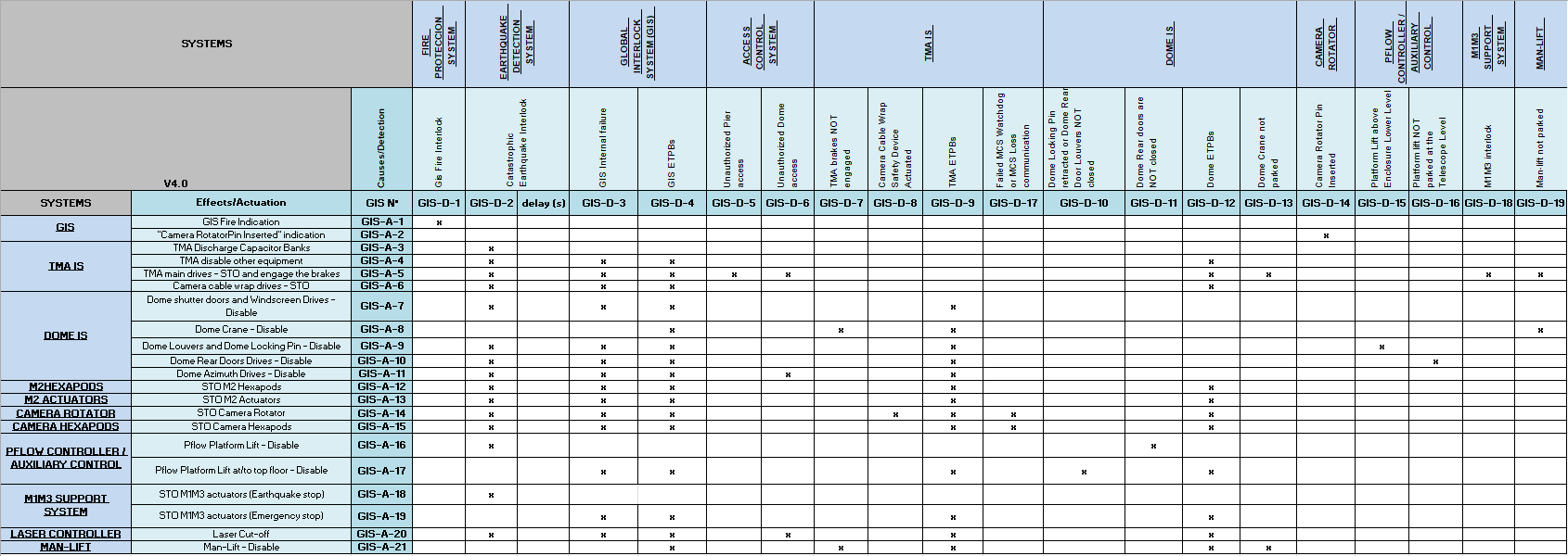
This interface has been made based on the I/O map defined in the GIS Table_v_4.xlsx, included in 092-308-E-Z_0004 document.
Reference document list
| No. | DOCUMENT | CODE | VERSION |
| 1 |
|
092-308-E-Z-00004 | 04 |
| 2 |
|
092-308-E-Z-00004 | 04 |
| 3 |
|
7186_GIS_0003 | 1.0 |
| 4 |
|
7186_GIS_0001 | 1.0 |
| 5 |
|
7186_GIS_0006 | 2.0 |
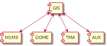
Communication GIS-Subsystems controller
The communication structure is vertical, it is only possible to link each CPU with the main controller and horizontal communication between the subsystem controllers is not contemplated.
ICD GIS-TMA
Inputs to GIS
GIS_D_7 TMA brakes NOT engaged
GIS_D_8 Camera cable wrap safety device activated
GIS_D_9 TMA ETPBs
GIS_D_17 Failed MCS watchdog or MCS loss communication
Output from GIS:
GIS_A_3 TMA Discharge Capacitors bank
GIS_A_4 TMA Disable other equipment
GIS_A_5 TMA main drives, STO and engage the brakes
GIS_A_6 Camera cable wrap drives STO
ICD GIS-M1M3
Inputs to GIS
GIS_D_18 M1M3 Interlock
Output from GIS:
GIS_A_18 M1M3 drives STO with Earthquake signal
GIS_A_19 M1M3 drives STO with Emergency stop
ICS GIS-DOME
Inputs to GIS
GIS_D_10 Dome Locking Pin retracted or Dome Rear Door Louvers NOT closed
GIS_D_11 Dome Rear doors are NOT closed
GIS_D_12 Dome ETPBs
GIS_D_13 Dome Crane not parkerd
Output from GIS:
GIS_A_7 Dome shutter and Windscreen drives STO or Disable
GIS_A_8 Dome crane drives STO or Disable
GIS_A_9 Dome Louvers and Dome Locking pin drives STO or Disable
GIS_A_10 Dome Rear Doors drives STO or Disable
GIS_A_11 Dome Azimuth drives STO or Disable
ICS GIS-AUX-TEL
In principle, the auxiliary telescope only needs to know the earthquake signal, so as not to duplicate the detector. This signal can be wired directly via a safe digital output of the GIS and in that case a SafetyNet communication with the GIS is not necessary. The other alternative is to establish the SafetyNet connection and define a communicated variable. In this case the ICD could be defined as,
Output from GIS:
GIS_A_22 Auxiliar telescope general STO