Deployment
Requested by: |
LSST |
|---|---|
Doc. Code: |
3151_MCS_0036 |
Editor: |
Julen Garcia |
Approved by: |
Alberto Izpizua |
Introduction
This document describes the deployment procedure for all elements in TMA.
The document has a section for each element in the TMA that needs deployment actions. In this sense the are deployment sections for:
Mount Control Computer
The computer in the control room is the responsible of running the Engineering User Interface, EUI, and the MtMount_operation_manager (developed in C++).
This computer also contains the database for the settings.
All those elements are described in next subsections.
The computer operating system is Centos 7 (centos-release-7-3.1611.el7.centos.x86_64).
‼️ This is the original setup for the MCC provide by Tekniker with the TMA. In 2026 this server is being replaced by a more modern server with Alma 9, for setting this up go here
EUI
The EUI is based on LabVIEW 2020 64 bits for Linux.
For deploying the EUI software the project called LSST_HMIs.lvproj is needed. It can be found in
this git repository.
Steps to run the EUI code:
Open the
LSST_HMIs.lvproj.Navigate to the Main folder at the project browser.
Open the
HMIMain_EUI.viand run it.This will launch the required tasks to run the EUI.
Configuration file
This file contains the general configuration of the application, the file can be found inside the git repo
HMIComputers/Configuration/HMIConfig.xml. As part of the deployment procedure, it is important to check that the
following items are correct before launching the app:
IPs values are correct. Check the value of the IPs and verify that the values are correct. The main IPs are:
TMAConnectionData.Remote_Adresshere the IP must point to the MCC machine, where the MTMount Operation Manager is going to run.AlarmsForHHDClientConnectionData.Remote_Adresshere the IP must point to the MCC machine, where the EUI will be running, this is used by the HHD.Database_Settings.Host_IPhere the IP must point to the MCC machine, where the settings database is located.TekNsvClientConfiguration0.Remote_Adresshere the IP must point to the TMA PXI, for reading the variables from it.TekNsvClientConfiguration1.Remote_Adresshere the IP must point to the AuxSystems PXI, for reading the variables from it.Actual_Commander_Data.Actual_commader_urlhere the IP of the commander variable must point to the TMA PXI.
Path values are correct. Check the value of the paths and verify that the values are correct. The main paths are:
Alarm_History_Paththis path refers to a directory where the alarm/warning history files will be stored.UsersDefinitionPaththis path refers to the file where the users for the EUI are defined.ErrorTaskDirectoryPaththis path refers to a directory where the software error files will be stored, this path is built as an array of folders, but works in the same way as the others.File_Saving_directory_paththis path refers to a directory where the telemetry history files will be stored.HMIWindowsTelemetryVariables_file_paththis path refers to the file that defines the variables for each window.TelemetryTopics_file_paththis path refers to the file that defines the variables for each topic.WindowTelemetryDirectoryPaththis path refers to a directory where the window telemetry files will be stored, this path is built as an array of folders, but works in the same way as the others.
Installing everything from scratch
This section describes how to install all the required software for the MCC. Each main task is explained in a specific section.
Requirements before starting the installation
For following the upcoming sections first get the following:
Centos 7 ISO image version: centos-release-7-3.1611.el7.centos.x86_64
LabVIEW 2015 32 bit installation files
LabVIEW 2020 32 & 64 bit installation files
WireFlow User Toolkit installation files
LabVIEW libraries from Tekniker
Configure the PC to be RAID 0
Open boot menu by pressing ESC on startup.
Select “SCU” from the menu.
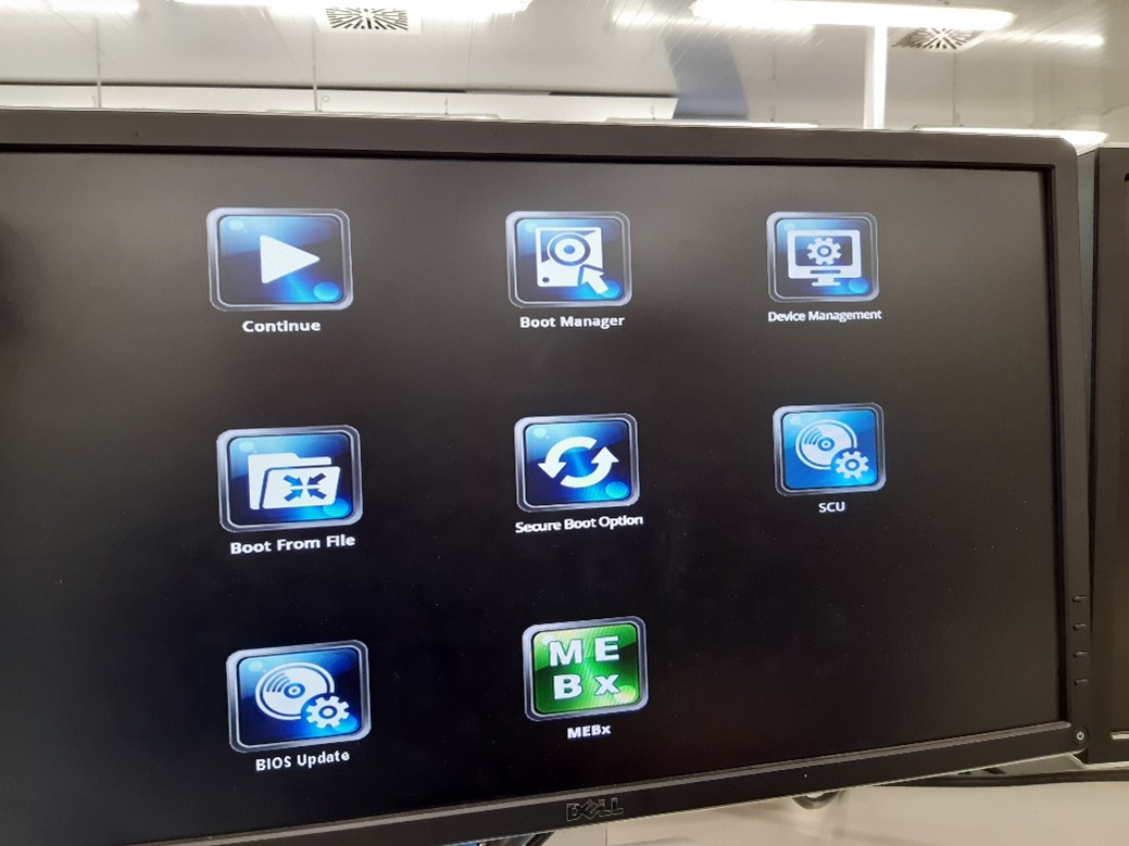
In the “SCU” go to Advanced > SATA Configuration.
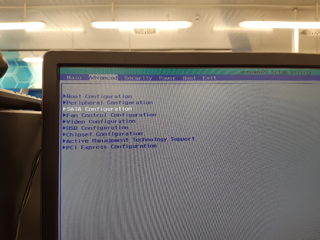
Select HDC Configure as “RAID”.
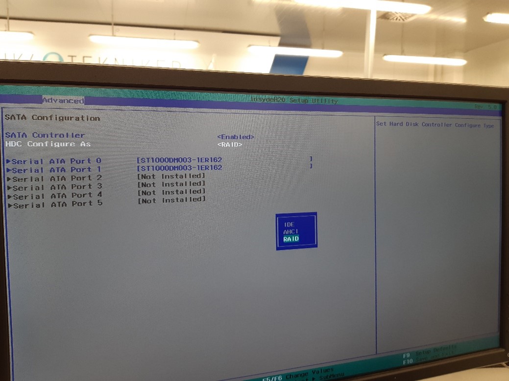
Save and exit.
The system reboots, now press
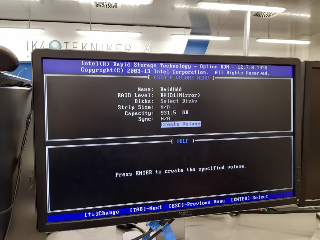
crtl + IThe RAID configuration will appear, select “Create RAID Volume”.
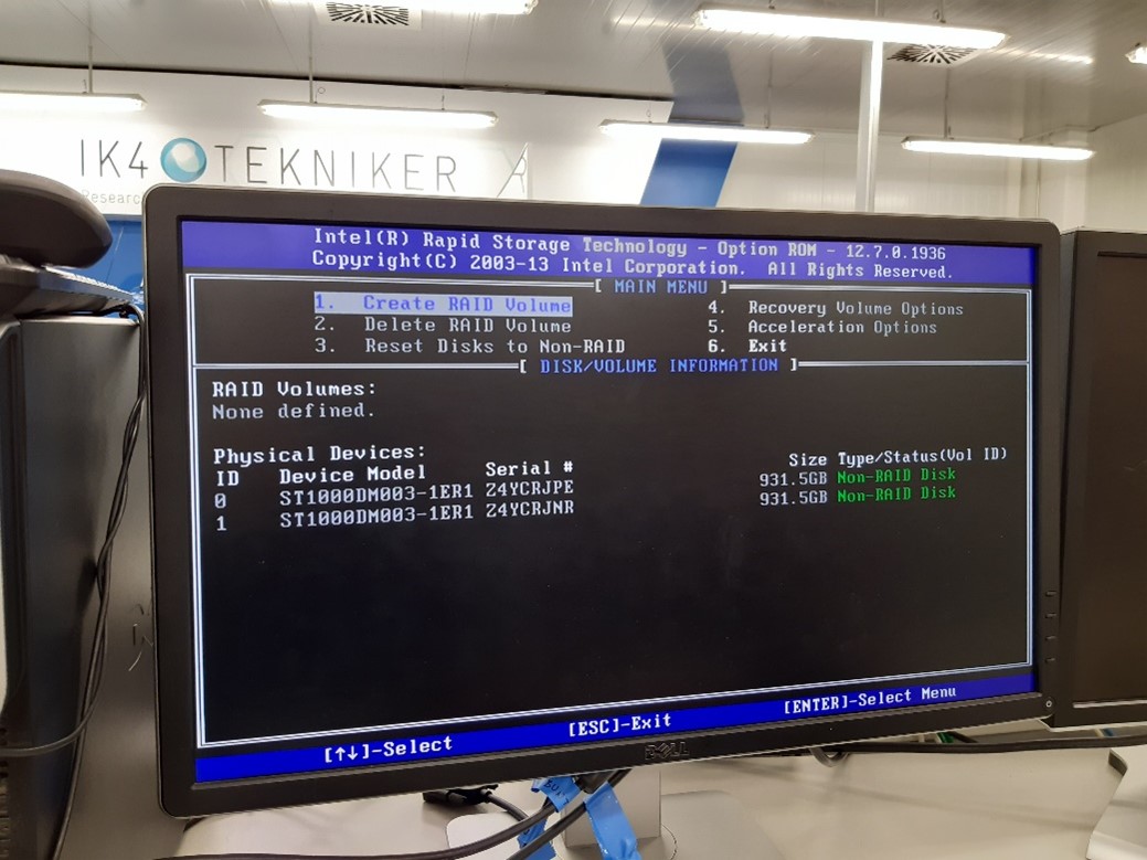
Select RAID 1 as the image bellow and press Create Volume:
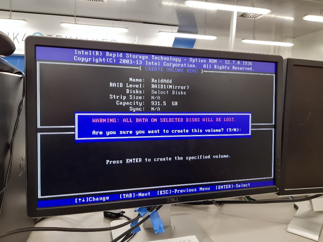
Exit the RAID menu.
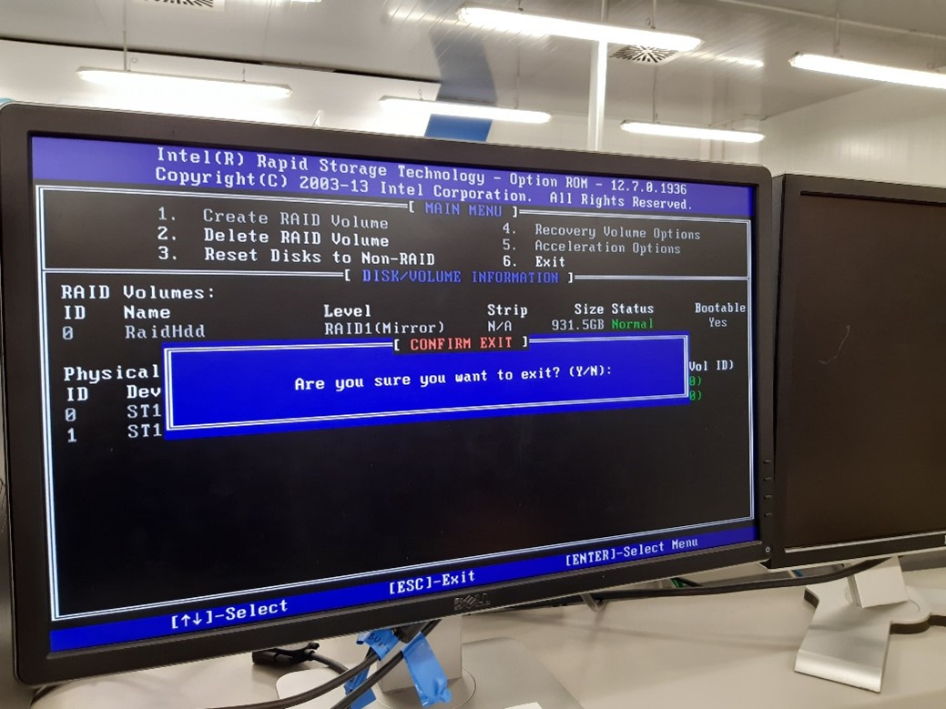
The RAID 1 is now configured, the Centos 7 installation can start.
Install Centos 7
Download the Centos 7 version: centos-release-7-3.1611.el7.centos.x86_64. Install it following the installation steps:
Run the Centos image from a USB drive.
Click install.
Select time zone.
Select keyboard layout.
Software selection: Gnome Desktop.
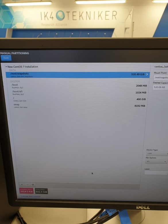
Installation Destination, select the RAID set and “I will configure partitioning”.
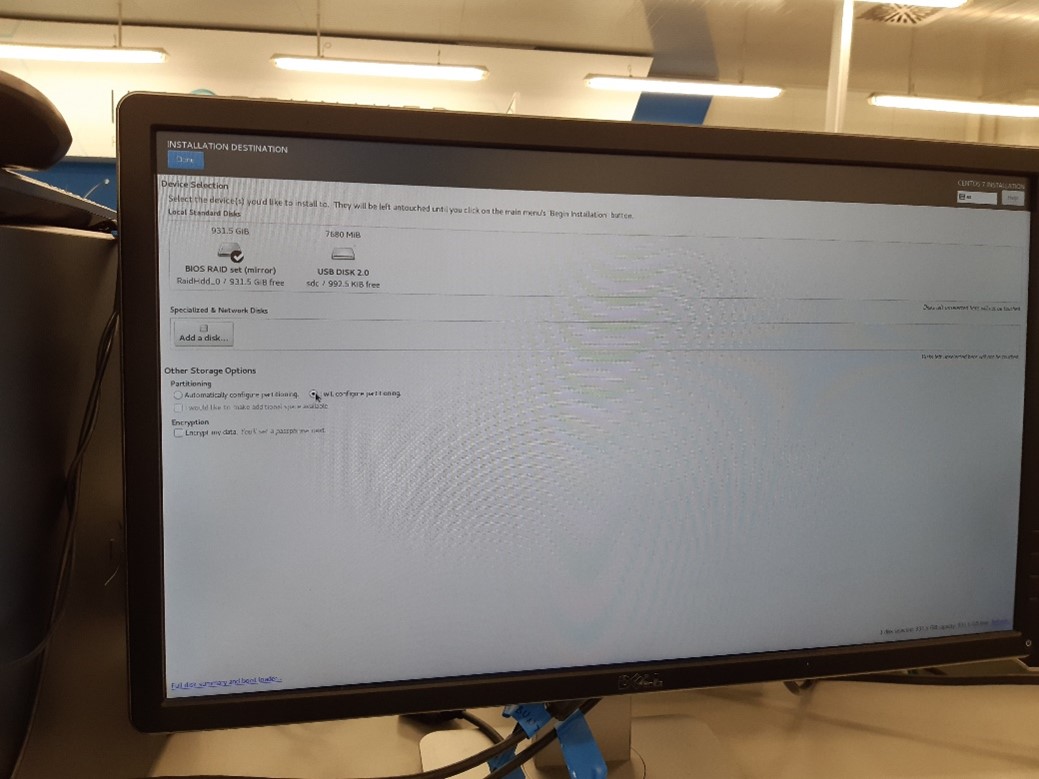
Select partitioning scheme LVM and create the partitions as the image bellow:
Network.
Host name: lsst.
Enable networks.
Internet interface set to DHCP
IP: DHCP
Mask: 255.255.255.0
Interface: enp0s25
TMA PXI interface set to:
IP: 192.168.209.200
Mask: 255.255.0.0
Interface: enp4s0
Telescope network interface:
IP: 192.168.2.200
Mask: 255.255.255.0
Interface: enp5s0
Begin installation.
Create root password.
Create admin user.
Name: lsst.
Set a password.
Select make this user admin.
Installation complete.
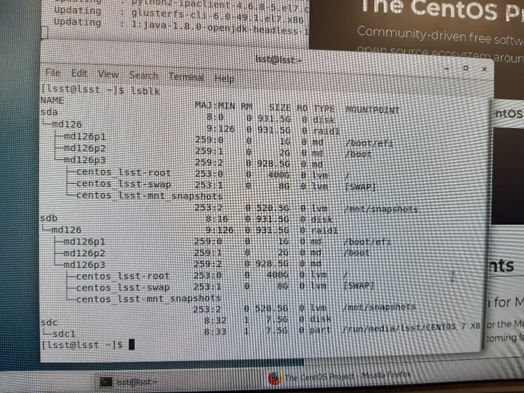
Check that the partitions are okay.
Execute:
lsblk
The result should look like the following:
Install git
The following steps were taken from this source.
Prerequisites: Before you start installing Git on CentOS 7. You must have the non-root user account on your Server or Desktop with sudo privileges.
Install Git on Centos: To install latest Git in CentOS you will need to enable GIT repository in CentOS.
First, create a new file inside /etc/yum.repos.d/ directory using following command:
sudo nano /etc/yum.repos.d/wandisco-git.repo
Copy the lines bellow inside the created file:
[wandisco-git]

name=Wandisco GIT Repository

baseurl=http://opensource.wandisco.com/centos/7/git/$basearch/

enabled=1

gpgcheck=1

gpgkey=http://opensource.wandisco.com/RPM-GPG-KEY-WANdisco
Now save and exit the editor typing CTRL+X then typing ‘Y’.
Next, Import GPG key for added repository key typing below command:
sudo rpm --import http://opensource.wandisco.com/RPM-GPG-KEY-WANdisco
Now install Git by typing following command:
sudo yum install git
Confirm the installation and check the version executing the following command:
git --versionThe output should be:
git version 2.18.0
Setting up git. To prevent warning every time you should configure it perfectly by using your Git information.
Set the global username for Git:
git config --global user.name "User Name"
Set global email for Git:
git config --global user.email "username@domain.com"
You can also change above configuration by editing .gitconfig file. To edit gitconfig file type:
nano ~/.gitconfig
Add motd
Include some identifying text into the /etc/motd file, for example:
███    ███  ██████  ██████
████  ████ ██      ██
██ ████ ██ ██      ██
██  ██  ██ ██      ██
██      ██  ██████  ██████
              by TEKNIKER
Install the MtMount Operation Manager
Follow the steps defined at the doc of this repository.
Install LabVIEW prerequisites
For installing LabVIEW installing the VI package manager is required, is a third-party tool used to install LabVIEW libraries. At the time this was made the VI package manager required the LabVIEW 2015 installed to run properly. A previous LabVIEW version as 2015 must be installed before installing a newer version, otherwise it throws an error. That’s why LV 2015 is installed as a prerequisite. VI package manager will be installed in this section.
Required libraries
sudo yum install glibc.i686 libstdc++.so.6 libXinerama.i686
sudo yum upgrade gnome-packagekit-common
sudo yum install libglvnd-glx-1.0.1-0.8.git5baa1e5.el7.i686
Install the full version of LabVIEW 2015 32 bit, this is the base that the VI package manager uses.
Follow the LabVIEW installation script and install everything.
sudo sh ./INSTALL
LabVIEW 2015 32 bit |
|---|
labview-2015-appbuild-32bit-15.0.1-1.i386 |
labview-2015-core-32bit-15.0.1-1.i386 |
labview-2015-desktop-32bit-15.0.1-1.i386 |
labview-2015-examples-32bit-15.0.1-1.i386 |
labview-2015-exe-32bit-15.0.1-1.i386 |
labview-2015-help-32bit-15.0.1-1.i386 |
labview-2015-pro-32bit-15.0.1-1.i386 |
labview-2015-ref-32bit-15.0.1-1.i386 |
labview-2015-rte-15.0.1-1.x86_64 |
labview-2015-rte-32bit-15.0.1-1.i386 |
Install LabVIEW 2020 64 bit Professional
For Linux there are multiple packages available when executing the installation script, install all the packages available. For doing so follow the installation script and say yes to all the packages.
Mount the iso:
sudo mkdir /mnt/iso
sudo mount -t iso9660 -o loop <LabVIEW_ISO_FileName>.iso /mnt/iso/
cd /mnt/iso
sudo ./INSTALL
When finished unmount the iso:
sudo umount /mnt/iso
LabVIEW 2020 64 bit |
|---|
labview-2020-appbuild.x86_64-18.0.1-1 |
labview-2020-core.x86_64-18.0.1-1 |
labview-2020-desktop.x86_64-18.0.1-1 |
labview-2020-examples.x86_64-18.0.1-1 |
labview-2020-exe.x86_64-18.0.1-1 |
labview-2020-help.x86_64-18.0.1-1 |
labview-2020-pro.x86_64-18.0.1-1 |
labview-2020-ref.x86_64-18.0.1-1 |
labview-2020-rte.x86_64-18.0.1-1 |
LabVIEW dependencies installation
Install VI package manager.
Download the VI package manager for Linux link.
Follow the installation guide. (As LabView 2015 runtime was installed previously, do not install LabView 2015 runtime again).
Download the latest VIPM configuration from here
Note that the file is big and is uploaded using git-lfs
Execute VI Package Manager.
Verify that VI Package Manager can connect to LabVIEW. If not:
Open LabView 2020 and change the LabVIEW configuration, going to Tools/options/VI Server and active the TCP/IP port and ensure that the port corresponds with the port at the VI Package Manager.
On the VI Package Manager, got to Tools->Options->LabView
Install the configuration file downloaded from github repo.
Making data sockets (NSVs) work when compiling the LabVIEW application
When building the compiled version of the LabVIEW application the data sockets were not working properly, we use data sockets to read the Network Shared Variables. For solving this problem a link to certain library must be created, for doing so, execute the following command (the solution comes from this LabVIEW forum):
sudo ln -s /usr/local/lib64/LabVIEW-2020-64/liblksock_impl.so /usr/local/lib64/liblksock_impl.so
Install docker
Docker installation steps, source
Install using the repository. Before you install Docker CE for the first time on a new host machine, you need to set up the Docker repository. Afterward, you can install and update Docker from the repository.
Set up the repository.
Install required packages. yum-utils provides the yum-config-manager utility, and device-mapper-persistent-data and lvm2 are required by the devicemapper storage driver.
sudo yum install -y yum-utils \
device-mapper-persistent-data \
lvm2
Use the following command to set up the stable repository.
sudo yum-config-manager \
--add-repo \
https://download.docker.com/linux/centos/docker-ce.repo
Install docker ce.
Install the latest version of Docker CE and containerd.
sudo yum install docker-ce docker-ce-cli containerd.io
Start docker.
sudo systemctl start docker
Verify that Docker CE is installed correctly by running the hello-world image.
sudo docker run hello-world
This command downloads a test image and runs it in a container. When the container runs, it prints an informational message and exits.
Install database
Follow the steps below (source Readme):
Set up the repository:
sudo yum install -y yum-utils

sudo yum-config-manager \
--add-repo \
https://download.docker.com/linux/centos/docker-ce.repo
Install:
sudo yum install docker-ce docker-ce-cli containerd.io
Add the user to docker users:
sudo usermod -aG docker $USER
Activate docker to automatically launch
sudo systemctl start docker
sudo systemctl enable docker
Reboot machine
sudo reboot
Install docker compose
sudo curl -L "https://github.com/docker/compose/releases/download/1.24.0/docker-compose-$(uname -s)-$(uname -m)" -o /usr/local/bin/docker-compose

sudo chmod +x /usr/local/bin/docker-compose
Clone the repository to
/home/lsst/LSST
cd /home/lsst/LSST

git clone git@github.com:lsst-ts/ts_tma_mariadb-docker.git
Update repository:
cd /home/lsst/LSST/mariadb-docker

git pull
Go to
/home/lsst/LSST/mariadb-dockerStart the docker service:
docker-compose up -d
Get the last backup database available and copy it to:
./backupCopy the three files:
lsst_AppData-XXX.sql.gz
lsst_events-XXX.sql.gz
lsst_settings-XXX.sql.gz
Create database
sudo ./createdatabases.pl
Restore last backup database. The script will choose the most recent backup.
sudo ./restoredatabases.pl
Edit contrab file to execute the python code that generates the backups:
sudo crontab -e
Add the following lines (Note: that the paths may change for each specific installation.):
5 12 * * * /home/lsst/LSST/mariadb-docker/createbackup.pl

5 13 * * * docker run --rm -v /home/lsst/LSST/mariadb-docker/python:/script -v /home/lsst/LSST/mariadb-docker/backup:/backup python:3.7 python /script/main.py
Save and exit crontab editor.
Clone the HMI repository
Clone the code from the HMI repository.
cd /home/lsst/LSST/

git clone git@github.com:lsst-ts/ts_tma_labview_hmi-computers.git

cd HMIComputers

git submodule update --init --recursive --remote
Create soft link to the *.so that gets the TAI time:
sudo ln -s /home/lsst/LSST/HMIComputers/getclockslabview/getclockssharedobject/libGetClocks.so /usr/local/lib/libGetClocks.so
Follow the steps to run the EUI code:
Open the
LSST_HMIs.lvproj.Navigate to the Main folder at the project browser.
Open the
HMIMain_EUI.viand run it.This will launch the required tasks to run the EUI.
Install the ptp protocol
Firewall configuration for allowing the PTP protocol to work (source).
Get firewall zones
sudo firewall-cmd --get-zones
Get active zones
sudo firewall-cmd --get-active-zones
List everything in the active zone, in this case it was public
sudo firewall-cmd --zone=public --list-all
Configure the system firewall to allow access by PTP event and general messages to UDP ports 319 and 320 in the appropriate zone, in this case public zone.
sudo firewall-cmd --zone=public --add-port=319/udp --add-port=320/udp

sudo firewall-cmd --permanent --zone=public --add-port=319/udp --add-port=320/udp
Follow the steps defined here to configure the PTP (source).
Download the PTP libraries:
sudo yum install linuxptp
The ptp will be used as a service so the options file will manage the behavior of the ptp. The options file must be located in
/etc/sysconfig/ptp4lOPTIONS="-f /etc/ptp4l.conf"For connection as master or slave (actual configuration) the file is shown in next lines
[global]

verbose 1

time_stamping hardware

priority1 200

priority2 200

[enp4s0]
The priority1 and priority2 are chosen to be 200 to use as masterclock when running in standalone with PXIs, since the pxi will is set to 254 and the switch to 250. See
The section [enp4s0] defines the nic to use for ptp and it’s configuration.
Enable and start the service
sudo systemctl enable ptp4l

sudo systemctl start ptp4l
To synchronize the system clock with the ptp clock or vice versa the phc2sys service is used. The configuration of this service is done in the
/etc/sysconfig/phc2sysOPTIONS="-a -r -r"The second -r allows to sync the system clock with ptp clock when it is the master
Enable and start the service
sudo systemctl enable phc2sys

sudo systemctl start phc2sys
To check ptp status
systemctl status phc2sys

systemctl status ptp4l

sudo cat var/log/messages
Open ports for HHD communication
For sending and receiving data from/to the HHD some tcp ports must be opened. To do so follow these steps:
Execute this command to open the right ports:
sudo firewall-cmd --zone=public --add-port=50006/tcp --permanent --zone=public --add-port=40005/tcp --permanent --zone=public --add-port=50005/tcp --permanent --zone=public --add-port=40006/tcp --permanent --zone=public --add-port=7500/tcp --permanent --zone=public --add-port=3306/tcp --permanent --zone=public --add-port=3015/tcp --permanent --zone=public --add-port=50013/tcp --permanent --zone=public --add-port=50015/tcp --permanent --zone=public --add-port=50035/tcp --permanent --zone=public --add-port=50016/tcp --permanent --zone=public --add-port=50017/tcp --permanent --zone=public --add-port=30005/tcp --permanent
Reload the firewall:
sudo firewall-cmd --reload
Check that the ports are opened:
$ sudo firewall-cmd --list-all

public (active)

target: default

icmp-block-inversion: no

interfaces: enp0s25 enp4s0 enp5s0

sources:

services: dhcpv6-client ssh

ports: 50006/tcp 40005/tcp 50005/tcp 40006/tcp 7500/tcp 3306/tcp 3015/tcp 50013/tcp 50015/tcp 50035/tcp 319/udp 320/udp 50016/tcp 50017/tcp 30005/tcp

protocols:

masquerade: no

forward-ports:

source-ports:

icmp-blocks:

rich rules:
Install VNC
Install VNC server
sudo yum install tigervnc-server
Set a password for the user
vncpasswd
Copy the template for the Systemd service
sudo cp /lib/systemd/system/vncserver@.service /etc/systemd/system/vncserver@:1.service
Edit the systemd service, here replace the
<USER>in the file with the user that is going to run it, in our caselsst.
sudo nano /etc/systemd/system/vncserver@\:1.service
Change the display resolution, for doing so modify the vncserver_wrapper file.
Open de vncserver_wrapper file:
sudo nano /usr/bin/vncserver_wrapper
Modify the following line from the vncserver_wrapper file adding
-geometry 1920x1080
/usr/sbin/runuser -l "$USER" -c "/usr/bin/vncserver ${INSTANCE} -geometry 1920x1080"
Enable and launch the service
sudo systemctl daemon-reload

sudo systemctl start vncserver@:1

sudo systemctl status vncserver@:1

sudo systemctl enable vncserver@:1
Remove old log files from the telemetry directory
Download the
main.pyscript from this repoMake 4 copies, name and modify them as follows :
removeOldAlarmFiles.py: in this copy replace the global variables as shown below:
files_directory = "/mnt/telemetry/AlarmHistory"
date_search_pattern = 'Alarm_File_(\d\d\d\d)_(\d\d)_(\d\d)'
months_to_keep = 12
removeOldErrorFiles.py: in this copy replace the global variables as shown below:
files_directory = "/mnt/telemetry/ErrorHistory"
date_search_pattern = 'SoftwareErrorFile_(\d\d\d\d)_(\d\d)_(\d\d)'
months_to_keep = 12
removeOldMemoryLoggingFiles.py: in this copy replace the global variables as shown below:
files_directory = "/mnt/telemetry/MemoryLogging"
date_search_pattern = 'MemoryLogging_(\d\d\d\d)_(\d\d)_(\d\d)'
months_to_keep = 2
removeOldWindowNavigationFiles.py: in this copy replace the global variables as shown below:
files_directory = "/mnt/telemetry/MemoryLogging"
date_search_pattern = 'WindowNavigationLogging_(\d\d\d\d)_(\d\d)_(\d\d)'
months_to_keep = 4
Call this 4 scripts from crontab
Edit crontab for the default user
crontab -eAdd the following lines:
35 9 * * * python3 /mnt/telemetry/AlarmHistory/removeOldAlarmFiles.py
40 9 * * * python3 /mnt/telemetry/ErrorHistory/removeOldErrorFiles.py
45 9 * * * python3 /mnt/telemetry/MemoryLogging/removeOldMemoryLoggingFiles.py
50 9 * * * python3 /mnt/telemetry/MemoryLogging/removeOldWindowNavigationFiles.py
Note that in this case the 4 scripts are placed in different places, for this crontab task to work the scripts must be placed there or the path to them must be changed when editing the crontab task
Connect to the VNC in the MCC
Connect to the Rubin VPN, if we are not in the local network already
Open a SSH tunnel to the server, use the following command:
ssh -L 5901:localhost:5901 -N lsst@139.229.178.30
Open the VNC client and connect to the following direction:
127.0.0.1:5901Enter the VNC server password.
Done you are now in the server user interface.
Development PC
This section refers to the computer used to deploy the code to the PXIs. This computer must be a Windows computer. It needs to have LV 2020 installed, as well as the following packages (version of packages not updated):
INSTALLED SOFTWARE |
VERSION |
|---|---|
CompactRIO |
20.0.0 |
C Series Module Support |
20.0.0 |
CVI Runtime |
17.0.0 |
NI-DAQmx Device Driver |
20.0.0f0 |
NI-DAQmx ADE Support |
20.0.0 |
NI-DAQmx MAX Configuration |
20.0.0 |
NI Script Editor |
20.0 |
NI-DMM |
|
NI 408x Device Support |
20.0 |
Configuration Support |
20.0 |
Development Support |
20.0 |
NI 407x, NI 406x, and NI 4050 Device Support |
20.0 |
Runtime Support |
20.0 |
NI-FGEN |
|
Configuration Support |
20.0 |
Development Support |
20.0 |
Runtime |
20.0 |
FGEN Soft Front Panel |
20.0 |
NI-488.2 Runtime |
20.0.0 |
NI-488.2 |
20.0.0 |
Vision Common Resources |
20.0.0 |
Image Processing and Machine Vision |
20.0.0.49152 |
Image Services |
20.0.0.49152 |
NI-Industrial Communications for EtherCAT |
20.0.0f0 |
NI I/O Trace |
20.0.0f0 |
IVI Compliance Package |
20.0 |
LabVIEW 2020 (64-bit) |
20.0.0 |
Control Design and Simulation Module |
20.0.0 |
MathScript RT Module |
20.0.0 |
Report Generation Toolkit For Microsoft Office |
20.0.0 |
Sound and Vibration Measurement Suite |
20.0.0 |
Sound and Vibration Toolkit |
20.0.0 |
Unit Test Framework Toolkit |
20.0.0 |
VI Analyzer Toolkit |
20.0.0 |
LabVIEW Run-Time 2012 SP1 f9 |
12.0.1 |
LabVIEW Runtime 2012 SP1 f9 (64-bit) |
12.0.1 |
Measurement & Automation Explorer |
20.0.0f0 |
Measurement Studio |
Visual Studio 2005 Support - See individual versions below. |
DotNET |
|
Common |
12.0.20.258 |
Vision |
|
Measurement Studio |
Visual Studio 2008 Support - See individual versions below. |
DotNET |
|
Common |
13.5.35.173 |
Common (64-bit) |
13.5.35.173 |
Vision |
|
Measurement Studio |
Visual Studio 2010 Support - See individual versions below. |
DotNET |
|
Common |
15.1.40.49152 |
Common (64-bit) |
15.1.40.49152 |
NI-USI |
15.0.2.6343 |
NI-DCPower |
|
Configuration Support |
16.0 |
Development Support |
16.0 |
Runtime |
16.0 |
NI-DCPower Soft Front Panel |
15.2 |
NI-HSDIO |
|
Configuration Support |
16.0 |
Development Support |
16.0 |
Runtime |
16.0 |
NI-HWS |
16.0.0 |
NI PXI Platform Services Configuration |
16.0.0f0 |
NI PXI Platform Services Runtime |
16.0.0f0 |
NI-RIO |
16.0.0 |
NI R Series Multifunction RIO |
16.0.0 |
NI-Sync Runtime |
16.0.0f0 |
NI-Sync |
16.0.0f0 |
NI-TimeSync |
16.0.0f0 |
FlexRIO |
16.0.0f0 |
NI-PAL Software |
16.0.0 |
NI 1588-2008 Network Management 16.0.0 |
16.0.0f0 |
NI Reconfigurable Oscilloscopes |
|
Runtime 16.0 |
16.0 |
NI-SCOPE |
|
Configuration Support |
16.0 |
Development Support |
16.0 |
Runtime |
16.0 |
SCOPE Soft Front Panel |
15.1 |
NI-Serial Runtime |
15.0.0f0 |
NI-Serial Configuration |
15.0.0f0 |
NI SignalExpress |
15.0 |
NI-SWITCH |
16.0 |
SwitchCA1, 2 & 3 Device Support |
16.0 |
SwitchCA4 Device Support |
16.0 |
Configuration Support |
16.0 |
Development Support |
16.0 |
Runtime |
16.0 |
Soft Front Panel |
16.0 |
Switch Executive |
15.1.0.49152 |
NI System Configuration |
16.0.0f0 |
NI-TClk |
16.0 |
TestStand 2016 |
2016 |
TestStand Runtime |
16.0.0.185 |
TestStand Sequence Editor |
16.0.0.185 |
TestStand 2016 (64-bit) |
2016 |
TestStand Runtime |
16.0.0.185 |
TestStand Sequence Editor |
16.0.0.185 |
TestStand AddOns |
TestStand Shared AddOns |
NI-VISA |
16.0 |
NiVisaServer.exe |
16.0.0.49152 |
NIvisaic.exe |
16.0.0.49152 |
NI-VISA Runtime |
16.0 |
Vision Builder AI 2015 f1 (64-bit) |
15.1.0 |
Vision Builder AI 2015 f1 (32-bit) |
15.1.0 |
Vision Development Module |
16.0.0 |
Runtime Support 2016 |
16.0.0 |
Development Support 2016 |
16.0.0 |
Vision Assistant (32-bit) |
16.0.0 |
Vision Assistant (64-bit) |
16.0.0 |
LabVIEW |
20.0.0 |
Advanced Signal Processing Toolkit |
16.0.0 |
Control Design and Simulation Module |
16.0.0 |
Database Connectivity Toolkit |
16.0.0 |
DataFinder Toolkit |
16.0.06357 |
Datalogging and Supervisory Control |
16.0.0 |
Digital Filter Design Toolkit |
16.0.0 |
FPGA |
16.0.0 |
MathScript RT Module |
16.0.0 |
NI SoftMotion |
16.0.0 |
Real-Time |
16.0.0 |
Real-Time Trace Viewer - LabVIEW 2016 Support |
16.0.0 |
Report Generation Toolkit For Microsoft Office |
16.0.0 |
Sound and Vibration Measurement Suite |
16.0.0 |
Sound and Vibration Toolkit |
16.0.0 |
Statechart Module |
16.0 |
Unit Test Framework Toolkit |
16.0.0 |
VI Analyzer Toolkit |
16.0.0 |
Vision Development Module |
16.0.0 |
LabVIEW Run-Time 2013 SP1 f6 |
13.0.1 |
LabVIEW Run-Time 2014 SP1 f5 |
14.0.1 |
LabVIEW Run-Time 2015 SP1 f3 |
15.0.1 |
LabVIEW Run-Time 2016 |
16.0.0 |
LabVIEW Runtime 2013 SP1 f6 (64-bit) |
13.0.1 |
LabVIEW Runtime 2014 SP1 f6 (64-bit) |
14.0.1 |
LabVIEW Runtime 2015 SP1 f3 (64-bit) |
15.0.1 |
LabVIEW Runtime 2016 (64-bit) |
16.0.0 |
The following modules are not included with the LabVIEW installer and must be downloaded:
LabVIEW dependencies
Install VI package manager if it was not installed when installed LabVIEW
Download the VI package manager for Windows.
Follow the installation guide
Execute VI Package Manager.
Verify that VI Package Manager can connect to LabVIEW. If not:
Open LabVIEW 2020 and change the LabVIEW configuration, going to Tools/options/VI Server and active the TCP/IP port and ensure that the port corresponds with the port at the VI Package Manager.
On the VI Package Manager, got to Tools->Options->LabVIEW
Install the packages contained in the VIPM configuration file located at this repo
Note that as the file is big it is uploaded as a Git LFS this means that when pulling the file the Git extension for versioning large files must be installed and configured for the repo.
Fix WireFlow addon for the HHD
There is a bug when building the WireFlow user management library for the HHD OS. To solve it follow these steps:
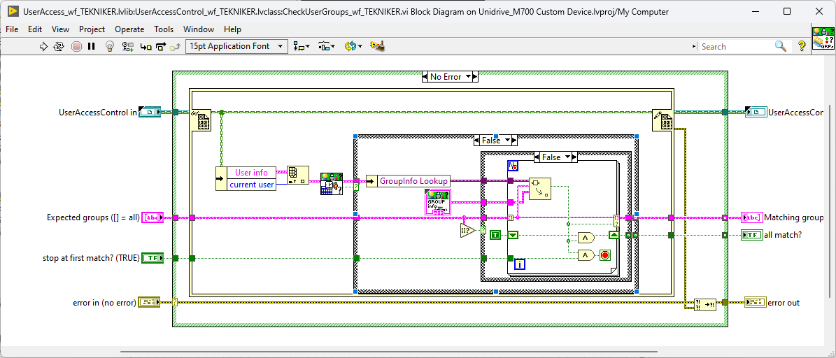
WF User Access Toolkit (FUNDACION TEKNIKER)must be installed using the VIPM configuration package from the previous stepLocate the VI that needs to be updated:
VI is:
C:\Program Files (x86)\National Instruments\LabVIEW 2020\vi.lib\addons\WireFlow\_AD0078-UAT (TEKNIKER)\runtime\EasyAccess\CheckUserGroups_wf_TEKNIKER.viPassword: rodastenrodasten
Once unlocked it should look like this:
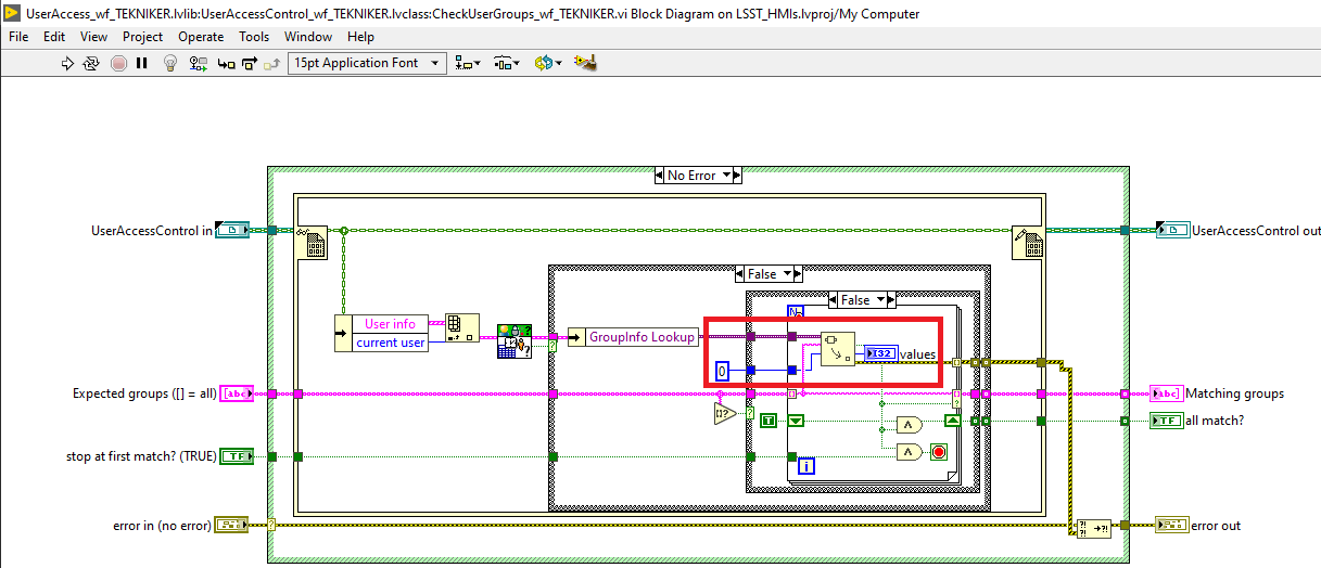
Modify the code inside the VI.
Remove the cluster constant below the unbundle by name that says GroupInfo Lookup and place a I32 constant
Create an I32 indicator
Once the changes are done, the block diagram should look like this:
HHD
Steps for setting up the Handheld Device.
Download the HMI repository
Open the HMI project.
Build the HHD application.
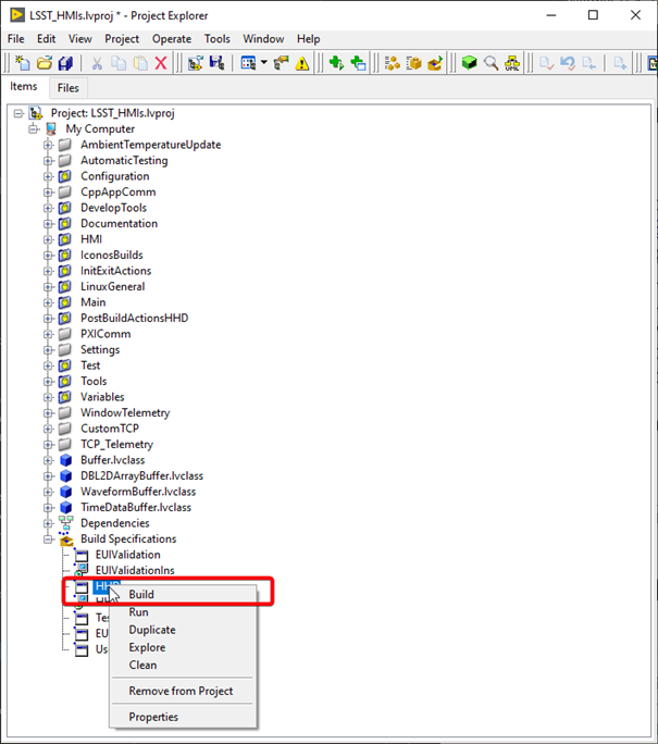
Build the HHD installer.
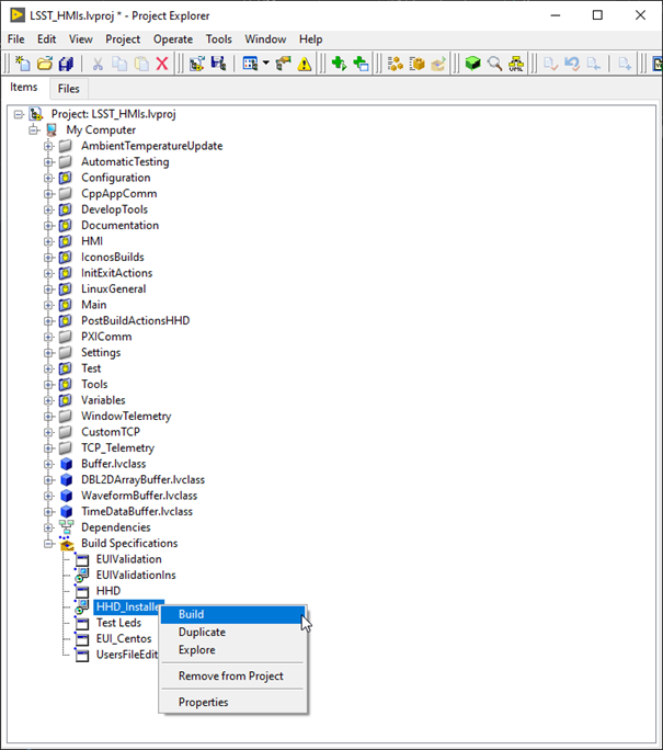
Execute the installer at the HHD.
Configure the HHD IP using the “CommArchitecture” document.
Configure the HHD application to run on start up.
TMA PXI
TMA PXI set up
Ensure that the PXI is configured as shown in Table 3 and has the software from Table 4 installed.
SYSTEM CONFIGURATION |
|
|---|---|
Hostname |
TMA-PXI |
DNS Name |
TMA-PXI |
Vendor |
National Instruments |
Model |
PXIe-8880 |
Serial Number |
2F23AA3D |
Firmware Version |
8.8.0f0 |
Operating System |
NI Linux Real-Time x64 4.14.146-rt67-cg-8.0.0f1-x64-139 |
System Start Time |
05/09/2022 15:48:05 |
Comments |
None |
Locale |
English |
Halt on IP failure |
False |
INSTALLED SOFTWARE |
VERSION |
|---|---|
NI Scan Engine |
9.0.0.49152-0+f0 |
LabVIEW Real-Time |
20.0.0.49154-0+f4 |
Network Streams |
20.0.0.49156-0+f4 |
Run-Time Engine for Web Services |
20.0.0.49152-0+f0 |
Variable Legacy Protocol Support |
5.12.0.49154-0+f2 |
NI PXI Platform Services |
20.0.0.49152-0+f0 |
NI-Watchdog |
20.0.0.49152-0+f0 |
Variable Legacy Server Support |
5.12.0.49154-0+f2 |
Variable Client Support for LabVIEW RT |
20.0.0.49153-0+f1 |
NI-RIO IO Scan |
20.0.0.49152-0+f0 |
NI System Configuration |
20.0.0.49152-0+f0 |
NI-Industrial Communications for EtherCAT |
20.0.0.49152-0+f0 |
NI System Configuration Remote Support |
20.0.0.49152-0+f0 |
NI-RIO |
20.0.0.49153-0+f1 |
NI-RIO Server |
20.0.0.49153-0+f1 |
WebDAV Server |
20.0.0.49152-0+f0 |
NI Scan Engine |
9.0.0.49152-0+f0 |
TMA Copy required files to the PXI
In addition to what is described in this section, check here
TMA Libraries
Copy the following libraries to the /usr/local/lib folder inside the PXI. These can be found here
Library list:
EIB8Driver32.so*libEIB8Driver.so*libGetClocks.so*libaci.so*libcrypto.so.1.0.0*libmlpi.so*libssl.so.1.0.0*libtrajectory.so*lvimptsl.so*
MLPI files
First copy the libmlpi.so to /usr/local/lib and then create a softlink in the /c/ni-rt folder called system, as follows.
cd /c/ni-rt

ln -s /usr/local/lib/ system
Add motd for TMA-PXI
Include some identifying text into the /etc/motd file, for example:
████████ ███    ███  █████      ██████  ██   ██ ██
   ██    ████  ████ ██   ██     ██   ██  ██ ██  ██
   ██    ██ ████ ██ ███████     ██████    ███   ██
   ██    ██  ██  ██ ██   ██     ██       ██ ██  ██
   ██    ██      ██ ██   ██     ██      ██   ██ ██
                                      by TEKNIKER
TMA PTP configuration
Follow next steps to configure the ptp in the PXI.
Install ptp
opkg install linuxptp
Copy the
ptp4l.confto/etc/ folder. In the configuration file shown next the eno1 is the name of the main network interface
[global]

verbose 1

time_stamping hardware

priority1 250

priority2 250

[eno1]
Copy the
ptpScriptto the folderetc/init.d
#!/bin/bash

NAME="PTP DAEMON"
PIDFILE=/var/run/ptpdaemon.pid
do_start() {
/sbin/start-stop-daemon --start --pidfile $PIDFILE --make-pidfile --background --chuid admin --exec /usr/bin/ptp4l -- -f /etc/ptp4l.conf
}
do_stop() {
/sbin/start-stop-daemon --stop --pidfile $PIDFILE --verbose
}
case "$1" in
start)
echo "Starting $NAME"
do_start
;;
stop)
echo "Stopping $NAME"
do_stop
;;
restart)
echo "Restarting $NAME"
do_stop
do_start
;;
*)
echo "Usage: $0 {start|stop|restart}"
exit 1
;;
esac
exit 0
Copy the
phcScriptto the folderetc/init.d
#!/bin/bash

NAME="PHC DAEMON"
PIDFILE=/var/run/phcdaemon.pid
do_start() {
/sbin/start-stop-daemon --start --pidfile $PIDFILE --make-pidfile --background --chuid admin --exec /usr/bin/phc2sys -- -a -r
}
do_stop() {
/sbin/start-stop-daemon --stop --pidfile $PIDFILE --verbose
}
case "$1" in
start)
echo "Starting $NAME"
do_start
;;
stop)
echo "Stopping $NAME"
do_stop
;;
restart)
echo "Restarting $NAME"
do_stop
do_start
;;
*)
echo "Usage: $0 {start|stop|restart}"
exit 1
;;
esac
exit 0
Make the files executables with chmod +x (both files)
chmod +x /etc/ptp4l.conf

chmod +x /etc/init.d/ptpScript

chmod +x /etc/init.d/phcScript
Install as startup script with default settings using
/usr/sbin/update-rc.d -f ptpScript defaults
Reboot target and check that PTP is running
pmc -u -b 0 'GET TIME\_STATUS\_NP'

cat /var/log/messages
TMA Deploying the code to the PXI
Steps for deploying the code to the TMA PXI:
Download the PXI repository
Open the
LSST_MainControllerPXI.lvproj.Open the Main.
Solve the requested dependencies if they appear.
Close the main.
Save all the request files.
Configure etherCAT ring.
Connect just 1 end of the etherCAT ring, recommended 4 slot B port cable connected and 3 slot B port disconnected.
To ensure that the ethercat line is displayed correctly the ESI files from the repo must be imported to labview.
Right click on the ethercat master -> Utilities -> Import Device Profiles…
Here select the ESI files to import. Import all the files from the this folder
Select only the import to the host computer option.
Click import.
Close the window.
Deploy the etherCAT master to the PXI.
Connect the etherCAT ring, if the recommended port was disconnected connect the 3 slot B port cable.
Execute the EtherCAT_RingConfig.vi, from this folder
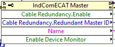
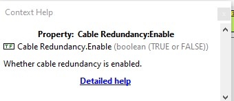
Check if the redundancy is active, if active skip next 2 steps, usually is not.
Restart PXI.
Execute the EtherCAT_RingConfig.vi, from this folder
Check if the redundancy is active, at this step it must be active.
Check online master state to ensure that all devices are okay.
If all the devices are okay the ring is ready.
Build the rtexe.
Deploy the rtexe to the target and set it to run on start up.
EIB Configuration files
For using the EIB TMA PXI must have the EIB configuration file located inside the PXI. The default path is: /c/Configuration/EIB multi_ext.txt this can be changed by a setting from the database.
Copy the file from the PXIController\ESIFiles\EIB folder to the PXI using scp.
Axes PXI
Axes PXI set up
Ensure that the PXI is configured as shown in Table 5 and has the software from Table 6 installed.
SYSTEM CONFIGURATION |
|
|---|---|
Hostname |
AxesPXI |
DNS Name |
AxesPXI |
Vendor |
National Instruments |
Model |
PXIe-8880 |
Serial Number |
2F23EB99 |
Firmware Version |
8.8.0f0 |
Operating System |
NI Linux Real-Time x64 4.14.146-rt67-cg-8.0.0f1-x64-139 |
System Start Time |
27/06/2019 11:42:28 |
Comments |
None |
Locale |
English |
Halt on IP failure |
False |
INSTALLED SOFTWARE |
VERSION |
|---|---|
NI Scan Engine |
9.0.0.49152-0+f0 |
LabVIEW Real-Time |
20.0.0.49154-0+f4 |
Network Streams |
20.0.0.49156-0+f4 |
Network Variable Engine |
20.0.0.49153-0+f1 |
Run-Time Engine for Web Services |
20.0.0.49152-0+f0 |
NI PXI Platform Services |
20.0.0.49152-0+f0 |
NI-Watchdog |
20.0.0.49152-0+f0 |
Variable Client Support for LabVIEW RT |
20.0.0.49153-0+f1 |
NI-RIO IO Scan |
20.0.0.49152-0+f0 |
NI System Configuration |
20.0.0.49152-0+f0 |
NI-Industrial Communications for EtherCAT |
20.0.0.49152-0+f0 |
NI System Configuration Remote Support |
20.0.0.49152-0+f0 |
NI-RIO |
20.0.0.49153-0+f1 |
NI-RIO Server |
20.0.0.49153-0+f1 |
WebDAV Server |
20.0.0.49152-0+f0 |
Axes Copy required files to the PXI
In addition to what is described in this section, check here
Axes Libraries
Copy the following libraries to the /usr/local/lib folder inside the PXI.
Library list:
libGetClocks.so*libaci.so*libssl.so.1.0.0*libtrajectory.so*lvimptsl.so*
Add motd for AXES-PXI
Include some identifying text into the /etc/motd file, for example:
 █████  ██   ██ ███████ ███████     ██████  ██   ██ ██
██   ██  ██ ██  ██      ██          ██   ██  ██ ██  ██
███████   ███   █████   ███████     ██████    ███   ██
██   ██  ██ ██  ██           ██     ██       ██ ██  ██
██   ██ ██   ██ ███████ ███████     ██      ██   ██ ██
                                          by TEKNIKER
PTP configuration Axes
The PTP is configured in the same way as done for the TMA-PXI, see here.
Axes Deploying the code to the PXI
Steps for deploying the code to the TMA PXI:
Download the PXI repository
Open the
MainAxesPXI.lvproj.Open the Main.
Solve the requested dependencies if they appear.
Close the main.
Save all the request files.
Configure etherCAT ring.
Connect just 1 end of the etherCAT ring, recommended 4 slot B port cable connected and 3 slot B port disconnected.
To ensure that the ethercat line is displayed correctly the ESI files from the repo must be imported to labview.
Right click on the ethercat master -> Utilities -> Import Device Profiles…
Here select the ESI files to import. Import all the files from the this folder
Select only the import to the host computer option.
Click import.
Close the window.
Deploy the etherCAT master to the PXI.
Connect the etherCAT ring, if the recommended port was disconnected connect the 3 slot B port cable.
Execute the
EtherCAT_RingConfig.vi, from this folderCheck if the redundancy is active, if active skip next 2 steps, usually is not.
Restart PXI.
Execute the
EtherCAT_RingConfig.vi, from this folderCheck if the redundancy is active, at this step it must be active.
Check online master state to ensure that all devices are okay.
If all the devices are okay the ring is ready.
Build the rtexe.
Deploy the rtexe to the target and set it to run on start up.
Ethercat cRIO 9145
Steps for setting up the cRIO:
Open the
MainAxesPXI.lvproj.Connect to the PXI and change it to Configuration.
Navigate to the cRIO at the MainDrives EtherCAT Master build the MainFPGA.
Download the MainFPGA.
Trajectory generation
The trajectory generation is developed by Tekniker. The code is stored in this repo.
AuxSystems PXI
AuxSystems PXI set up
Ensure that the PXI is configured as shown in Table 5 and has the software from Table 6 installed.
SYSTEM CONFIGURATION |
|
|---|---|
Hostname |
AuxSystems |
DNS Name |
AuxSystems.local |
Vendor |
National Instruments |
Model |
PXIe-8880-Beckhoff |
Serial Number |
2F23EB99 |
Firmware Version |
8.8.0f0 |
Operating System |
NI Linux Real-Time x64 4.14.146-rt67-cg-8.0.0f1-x64-139 |
System Start Time |
27/06/2019 11:42:28 |
Comments |
None |
Locale |
English |
Halt on IP failure |
False |
INSTALLED SOFTWARE |
VERSION |
|---|---|
LabVIEW Real-Time |
20.0.0.49154-0+f4 |
Network Variable Engine |
20.0.0.49153-0+f1 |
Run-Time Engine for Web Services |
20.0.0.49152-0+f0 |
Variable Legacy Protocol Support |
5.12.0.49154-0+f2 |
Variable Legacy Server Support |
5.12.0.49154-0+f2 |
Variable Client Support for LabVIEW RT |
20.0.0.49153-0+f1 |
NI System Configuration Remote Support |
20.0.0.49152-0+f0 |
WebDAV Server |
20.0.0.49152-0+f0 |
AuxSystems Copy required files to the PXI
In addition to what is described in this section, check here
AuxSystems Libraries
Copy the following libraries to the /usr/local/lib folder inside the PXI.
Library list:
libGetClocks.so*
Add motd for AUX-PXI
Include some identifying text into the /etc/motd file, for example:
 █████  ██    ██ ██   ██     ██████  ██   ██ ██
██   ██ ██    ██  ██ ██      ██   ██  ██ ██  ██
███████ ██    ██   ███       ██████    ███   ██
██   ██ ██    ██  ██ ██      ██       ██ ██  ██
██   ██  ██████  ██   ██     ██      ██   ██ ██
                                   by TEKNIKER
AuxSystems PTP configuration
The PTP is configured in the same way as done for the TMA-PXI, see here.
AuxSystems deploying the code to the PXI
Steps for deploying the code to the TMA PXI:
Download the PXI repository
Open the
AuxSystemsController.lvproj.Open the Main.
Solve the requested dependencies if they appear.
Close the main.
Save all the request files.
Build the rtexe.
Deploy the rtexe to the target and set it to run on start up.
Closing the ethercat ring
Hardware configuration
Note that for closing the ethercat ring, two compatible ports of the PXI must be used, these ports must be configured as follows (for this step the NI MAX must be used):
Master port, the one that will be wired to the first IN port of the first slave, the ethercat ID must be smaller than the one for the return. For example ID = 1.
Redundancy port, the one that will close the ring coming from the last slave’s OUT port, the ethercat ID must be higher than the one for the master port. For example ID = 2.
Software steps
Steps for closing the ethercat ring:
Connect the ethercat line start point to the master port and DON’T connect anything to the redundancy port.
Create a blank project with the scan engine configuration for the target copied from the final project (TMA-PXI or AXES-PXI projects depending on the target).
Deploy the empty target configuration, just with the scan engine configuration to the target and reboot. This is to have a clean start, with no ethercat masters on the target.
Open the project that corresponds to the current target and deploy the master configuration to the master port ID from the LabVIEW project. Leave the scan engine in ACTIVE after the deploy
Using the NI Distributed System Manager, check that the target has the ethercat master deployed and that is in active
Disconnect the LabVIEW project from the target
Using the NI Distributed System Manager, set the scan engine to configuration
Connect the ethercat return wire to the redundancy port in the target
Using the NI Distributed System Manager, do a refresh modules
If everything went correctly the redundancy should be active now. There is a property from the ethercat master that can be read from LabVIEW that tells if the redundancy is active or not.
Using the NI Distributed System Manager, set the scan engine to active and now the ring is complete and active
After a reboot the PXI is not changed to active automatically and the redundancy is not active. Code in the target is implemented to perform the refresh modules, activate the redundancy, and set the scan engine to active.
Bosch Rexroth drive system
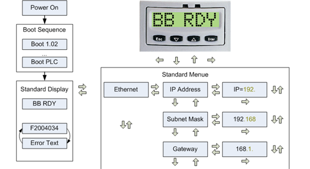
First the Ethernet configuration in the MLC must be set. Follow next steps to perform the IP change
Power on MLC
Move with
Enterfrom the standard display BB STOP to the ETHERNET display.Press
Enteragain to go to the IP address.Press
Enteragain to change the preset address. The IP address must be 192.168.212.3Change its section of the IP address value with
DOWNorUPand continue to next section withEnter. The individual blocks flash to visualize the change. This is first change the sectionXXX.to192., then192.XXX.to192.168.and so on.After the fourth block, press
Enterto trigger the query: “OK : ?. Confirm withEnter. The change is applied and the ETHERNET display opens. IfEscis pressed during the change, the change is discarded!Change the subnet mask to 255.255.255.0 and the gateway to 192.168.212.253 address analogously
Reboot MLC to apply Ethernet settings.
Now, Indraworks Engineering tool is able to connect to MLC. Follows next steps for setting up the configuration in the MLC.
Download the Indraworks repository
Open the indraworks project
Connect to the MLC from the indraworks tool and deploy the project
Watlow temperature controller
In this section steps for setting up the temperature controller can be found. The temperature controller is composed by two different components
RMC. The temperature controller itself
RMA. A communication module for RMC, that makes the RMC accessible using modus TCP.
Both are configured in the same way
Connect a RS485 cable to RMC or RMA
Connection to RMC in the button of the RMC
Data+ to Pin
Data- to Pin
Common to Pin
Connection to RMC in the button of the RMC
Data+ to Pin
Data- to Pin
Common to Pin
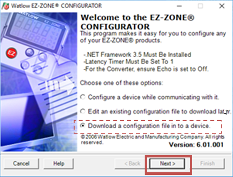
Download the configuration files placed in the repository
Open the tool EZ-Zone Configurator 6.1 and click
Nextin the welcome window with the optionDownload a configuration file in to a device
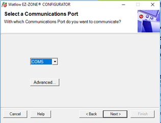
Select the proper com and click
Next
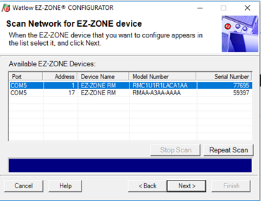
Chose the element to connect, RMC or RMA and click
Next
Chose the file
RMC_Configuration.wcffor RMCRMA_Configuration.wcffor RMA
Phoenix Contact IOs
Download the configuration files placed in the repository in the folder
\PXIController\ESIFiles\Phoenix\IOConfiguration.Connect to the desired header using a usb to micro usb cable. See images bellow to find the connection point in the IO header
Open startup+ from Phoenix Contact, v2.6.
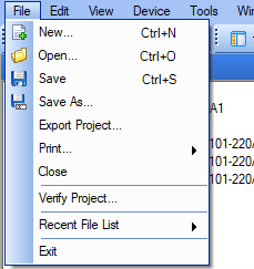
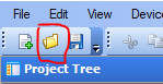
When opening chose to load an existing project or click open project form file menu or task bar
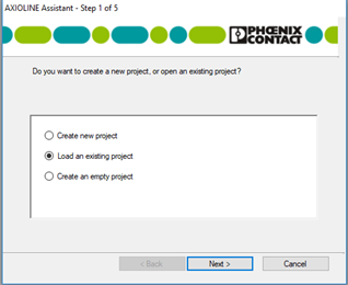
Navigate to file corresponding to connected IOs. The files are named with the name of the cabinet, and for cabinet TMA-AZ-CS-CBT-0101 there are two files, one with suffix 220A1 and the other with suffix 220A2 for modules with the same name inside this cabinet.
Chose the header and right click.
Select parameters->Download all parameters
CCW Aux Cabinet
There is a small cabinet for controlling the CCW when the CCW is not connected to the TMA. This cabinet contains a similar setup to the one of the TMA, but in a smaller scale.
CCWauxCC
This is the computer inside the cabinet that runs the EUI for the cabinet and the operation manager.
MtMount Operation Manager
Here the code is the same as for the TMA, but the configuration is not, that’s why there is a specific repo with the configuration for this computer-cabinet setup. CCWaux operation manager specific repo
Deploying the operation manager for the CCWaux:
Clone the repo into the CCWauxCC
Navigate into the folder
Bring up the docker image with the custom configuration from the repo ->
docker-compose up -dNote that the docker image is stored in github containers as a private repo, so for downloading a login into github is required with the right permissions
EUI for CCWaux
Here the code is the same as for the TMA, but the configuration is not.
Download the desired build for the EUI (latest version is recommended) from here
Extract the files at the desired location
Replace the following files and lines in the config files
Copy the files
CCWaux_HMIWindowsTelemetryVariables.iniandCCWaux_TelemetryTopicsConfiguration.inifrom the repo located inside the Configuration folder into the extracted filesdatafolder.Remove the files that won’t be needed ->
HMIWindowsTelemetryVariables.iniandTelemetryTopicsConfiguration.iniEdit the
HMIConfig.xml:Change the value of the CCWAuxMode field to TRUE
Change the value of the UsersDefinitionPath field to the path to the HMI_UserManagementFile.uat file, usually inside the installation
datafolderChange the value of the HMIWindowsTelemetryVariables_file_path field to the path to the CCWaux_HMIWindowsTelemetryVariables.ini file, usually inside the installation
datafolderChange the value of the TelemetryTopics_file_path field to the path to the CCWaux_TelemetryTopicsConfiguration.ini file, usually inside the installation
datafolderChange the value of the Database_Settings.IP field to the IP of the MCC 139.229.178.30
Change the value of the IP in Actual_Commander_Data.Actual_commader_url field to the IP of the cRIO 192.168.209.11
Change the value of the TekNSVtotalClients field to 1
Change the value of the IP in TekNsvClientConfiguration0.Remote_Adress field to the IP of the cRIO 192.168.209.11
Run the eui executable
Database for CCWaux
To reduce problems with the different settings, the same database is used for the CCW when connected to the CCWaux cabinet and to the TMA. For having this, the local port 3306 for the database is forwarded to the MCC using the firewall.
Enable firewall ->
sudo systemctl enable firewalldReboot machine ->
sudo rebootOpen database port, as well as other required ports
sudo firewall-cmd --zone=public --add-port=50006/tcp --permanent --zone=public --add-port=40005/tcp --permanent --zone=public --add-port=50005/tcp --permanent --zone=public --add-port=40006/tcp --permanent --zone=public --add-port=7500/tcp --permanent --zone=public --add-port=3306/tcp --permanent --zone=public --add-port=3015/tcp --permanent --zone=public --add-port=50013/tcp --permanent --zone=public --add-port=50015/tcp --permanent --zone=public --add-port=50035/tcp --permanent --zone=public --add-port=50016/tcp --permanent --zone=public --add-port=50017/tcp --permanent --zone=public --add-port=30005/tcp --permanent
sudo firewall-cmd --add-port=3306/tcp --add-port=319/udp --add-port=320/udp --permanent
sudo firewall-cmd --reload
Forward port
sudo firewall-cmd --add-forward-port=port=3306:proto=tcp:toport=3306:toaddr=139.229.178.30 --permanent
sudo firewall-cmd --zone=public --add-masquerade --permanent
sudo firewall-cmd --reload
The configuration should look like this:
$ sudo firewall-cmd --list-all
[sudo] password for lsst:
public (active)
  target: default
  icmp-block-inversion: no
  interfaces: em1 p1p1 p2p2
  sources:
  services: dhcpv6-client ssh
  ports: 319/udp 320/udp 50006/tcp 40005/tcp 50005/tcp 40006/tcp 7500/tcp 3306/tcp 50035/tcp
  protocols:
  masquerade: yes
  forward-ports: port=3306:proto=tcp:toport=3306:toaddr=139.229.178.30
  source-ports:
  icmp-blocks:
  rich rules:
Low level controller (cRIO)
RTEXE
This cabinet does not contain a PXI, as they are way too expensive for the purpose of this cabinet, that’s why the
low-level controller in this case is cRIO. Apart from the hardware difference, the code is almost the same for both the
TMA and the CCWaux. Both are stored in the same repo the only
difference is that the project for the CCWaux is the one called LSST_CCWAuxCRIOController.lvproj.
For building the rtexe is quite the same as for the main PXIs:
Download the repo
Open the project ->
LSST_CCWAuxCRIOController.lvprojOpen the Main.
Solve the requested dependencies if they appear.
Close the main.
Save all the request files.
Deploy the I/O module configuration
Build the rtexe.
Deploy the rtexe to the target and set it to run on start up.
Check the the cRIO started properly
admin@NI-cRIO-9030-01BE3F54:~# labviewmessages
2025-01-09T13:07:17.189+00:00 NI-cRIO-9030-01BE3F54 LabVIEW_Custom_Log: Version: 6.2.3
2025-01-09T13:07:19.181+00:00 NI-cRIO-9030-01BE3F54 LabVIEW_Custom_Log: Init CCWauxMain
2025-01-09T13:07:19.510+00:00 NI-cRIO-9030-01BE3F54 LabVIEW_Custom_Log: Initialized Variable server
2025-01-09T13:07:33.713+00:00 NI-cRIO-9030-01BE3F54 LabVIEW_Custom_Log: Ping to Safety OK
2025-01-09T13:07:34.216+00:00 NI-cRIO-9030-01BE3F54 LabVIEW_Custom_Log: Temp. OK
2025-01-09T13:07:49.232+00:00 NI-cRIO-9030-01BE3F54 LabVIEW_Custom_Log: DataBase OK
2025-01-09T13:07:52.636+00:00 NI-cRIO-9030-01BE3F54 LabVIEW_Custom_Log: CAR Initialized
2025-01-09T13:07:52.702+00:00 NI-cRIO-9030-01BE3F54 LabVIEW_Custom_Log: DiscreteStatereporting launched
2025-01-09T13:07:52.718+00:00 NI-cRIO-9030-01BE3F54 LabVIEW_Custom_Log: SubscribeSubsystem: DiscreteStateReporting MinimumCommand: 2501 MaximumCommand: 2599 QueueRefsValid: TRUE
2025-01-09T13:07:55.752+00:00 NI-cRIO-9030-01BE3F54 LabVIEW_Custom_Log: Safety launched
2025-01-09T13:07:55.838+00:00 NI-cRIO-9030-01BE3F54 LabVIEW_Custom_Log: SubscribeSubsystem: Safety MinimumCommand: 1801 MaximumCommand: 1899 QueueRefsValid: TRUE
2025-01-09T13:07:55.882+00:00 NI-cRIO-9030-01BE3F54 LabVIEW_Custom_Log: Safety launched - log to see errors
2025-01-09T13:07:55.883+00:00 NI-cRIO-9030-01BE3F54 LabVIEW_Custom_Log: SafetyTask_Started
2025-01-09T13:08:52.851+00:00 NI-cRIO-9030-01BE3F54 LabVIEW_Custom_Log: Bosch DC launched
2025-01-09T13:08:52.869+00:00 NI-cRIO-9030-01BE3F54 LabVIEW_Custom_Log: BoschPowerSupplyTask started
2025-01-09T13:08:52.894+00:00 NI-cRIO-9030-01BE3F54 LabVIEW_Custom_Log: SubscribeSubsystem: BoschPowerSupply MinimumCommand: 65535 MaximumCommand: 65535 QueueRefsValid: TRUE
2025-01-09T13:08:59.014+00:00 NI-cRIO-9030-01BE3F54 LabVIEW_Custom_Log: Bosch task launched
2025-01-09T13:08:59.039+00:00 NI-cRIO-9030-01BE3F54 LabVIEW_Custom_Log: SubscribeSubsystem: BoschTask MinimumCommand: 10357 MaximumCommand: 10357 QueueRefsValid: TRUE
2025-01-09T13:08:59.051+00:00 NI-cRIO-9030-01BE3F54 LabVIEW_Custom_Log: BoschTask started.
2025-01-09T13:08:59.311+00:00 NI-cRIO-9030-01BE3F54 LabVIEW_Custom_Log: CCW task launched
2025-01-09T13:08:59.363+00:00 NI-cRIO-9030-01BE3F54 LabVIEW_Custom_Log: SubscribeSubsystem: CCW MinimumCommand: 1001 MaximumCommand: 1099 QueueRefsValid: TRUE
2025-01-09T13:08:59.473+00:00 NI-cRIO-9030-01BE3F54 LabVIEW_Custom_Log: CCW initialization actions completed
admin@NI-cRIO-9030-01BE3F54:~#
For seeing the messages above the following alias is needed inside the
/home/admin/.bashrcfile ->alias labviewmessages="cat /var/log/messages | grep LabVIEW_Custom"
Libraries
Copy the following libraries to the /usr/local/lib folder inside the PXI.
Library list:
libGetClocks.so*libaci.so*libcrypto.so.1.0.0*libmlpi.so*libssl.so.1.0.0*
MLPI files
First copy the libmlpi.so to /usr/local/lib and then create a softlink in the /c/ni-rt folder called system, as follows.
cd /c/ni-rt

ln -s /usr/local/lib/ system
Configuration files
Add the needed configuration files in /c/Configuration, these are:
/c/Configuration/CAR_TCP/CommandTCP_Config.xml: taken from the repo insideESIFiles/CommandCommunicationTMAPXI/CommandTCP_Config.xml
/c/Configuration/DiscreteStatereporting/DiscreteStateReporting.json: taken from the repo insideESIFiles/DiscreteStateReporting/CCWaux/DiscreteStateReporting.json
/c/Configuration/Safety/Safety_ModBusMapping.txt: taken from the repo insideCCWAuxExpecificCode/Safety/MappingFilesSafety_ModBusMapping_ForReadWriteDefinition.txt: taken from the repo insideCCWAuxExpecificCode/Safety/MappingFilesServerConfig.ini: taken from the repo insideCCWAuxExpecificCode/Safety/MappingFiles
/c/Configuration/TekNSVs/ReceiverConfig.xml: taken from the repo insideESIFiles/TekNSV/TMA_PXI/ReceiverConfig.xml
After copying those files the configuration folder should look like this:
admin@NI-cRIO-9030-01BE3F54:/c/Configuration# ll -R
.:
total 28
drwxr-xr-x    6 lvuser   ni            4096 Dec  9 18:29 ./
drwxrwxr-x    4 lvuser   ni            4096 Mar 11  2021 ../
drwxrwxr-x    2 lvuser   ni            4096 Dec  9 16:17 CAR_TCP/
drwxr-xr-x    2 admin    administ      4096 Dec  9 16:20 DiscreteStateReporting/
drwxrwxr-x    2 lvuser   ni            4096 Dec  9 16:48 Safety/
drwxr-xr-x    2 admin    administ      4096 Dec  9 16:52 TekNSVs/

./CAR_TCP:
total 12
drwxrwxr-x    2 lvuser   ni            4096 Dec  9 16:17 ./
drwxr-xr-x    6 lvuser   ni            4096 Dec  9 18:29 ../
-rwxrwxrwx    1 lvuser   ni             564 Dec  9 16:18 CommandTCP_Config.xml*

./DiscreteStateReporting:
total 12
drwxr-xr-x    2 admin    administ      4096 Dec  9 16:20 ./
drwxr-xr-x    6 lvuser   ni            4096 Dec  9 18:29 ../
-rw-r--r--    1 admin    administ       371 Dec  9 16:32 DiscreteStateReporting.json

./Safety:
total 20
drwxrwxr-x    2 lvuser   ni            4096 Dec  9 16:48 ./
drwxr-xr-x    6 lvuser   ni            4096 Dec  9 18:29 ../
-rwxrwxr-x    1 lvuser   ni            2111 Jan  7 10:07 Safety_ModBusMapping.txt*
-rwxr-xr-x    1 lvuser   ni            1286 Jan  7 10:07 Safety_ModBusMapping_ForReadWriteDefinition.txt*
-rwxrwxrwx    1 lvuser   ni             128 Dec  9 16:35 ServerConfig.ini*

./TekNSVs:
total 12
drwxr-xr-x    2 admin    administ      4096 Dec  9 16:52 ./
drwxr-xr-x    6 lvuser   ni            4096 Dec  9 18:29 ../
-rwxr-xr-x    1 admin    administ       565 Dec  9 16:52 ReceiverConfig.xml*
admin@NI-cRIO-9030-01BE3F54:/c/Configuration#