MCS SW Design Report
Requested by: |
GHESA |
|---|---|
Doc. Code: |
3151_MCS_0002 |
Editor: |
Julen Garcia |
Approved by: |
Ismael Ruiz de Argandoña |
Introduction
This document contains the description of the software (SW) design of the TMA control system and it is divided into two main chapters. In the first one, the structure of all the SW programs forming the MCS are described. In the second one, the behavior of some of the most important tasks of these programs is detailed.
Reference documents
Document |
Code |
Version |
|---|---|---|
MCS Operation |
3151_MCS_0001 |
5 |
Technical Specification. PLCopen - Technical Committee 2 – Task Force. Function blocks for motion control |
1.1 |
Description of MCS functions and TMA subsystems
The TMA can be functionally divided into the following subsystems:
Azimuth axis. The azimuth axis must be controlled in position in order to perform the requested point to point and tracking movements. This implies managing the linear drives, their power supply and their thermal control, the encoder system, hydrostatic bearing system, hydraulic brakes and controlling the position of the cable wrap system
Altitude (elevation) axis.The elevation axis must be controlled in position in order to perform the requested point to point and tracking movements. This implies managing linear drives, their power supply and their thermal control, the encoder system, the hydrostatic bearing system, hydraulic brakes and locking pins
Balancing system. The four actuators forming the balancing system must be controlled in position. The position of each actuator will be defined when performing the TMA balancing operation by measuring the current consumption of the main drives
Mirror Cover system. The mirror cover system must be controlled in position in order to perform cover opening and closing operations. Four auxiliary actuators controlled in position have been added to block the cover in the retracted position.
Deployable platforms system. The retractable/deployable platforms are used for maintenance and can be commanded from the user interface.
Camera cable wrap system. The camera cable wrap system is controlled in position and is commanded by the CSC to follow the position of the camera rotator.
Cabinet thermal control system. The cabinet thermal control system must control the surface temperature of the electrical cabinets while maintaining the internal temperature inside the operation range of the contained equipment.
Locking pins system. The two actuators, there are two for redundancy, are for locking the elevation axis into the parking positions: zenith or horizon.
Main Power Supply system. This is the power supply for the main drives uses to move Azimuth and Elevation axes.
OSS. This is the Oil Supply System, responsible of keeping the telescope floating on an oil film to reduce friction.
Azimuth Cable Wrap system. Is commanded in position by the azimuth axis, to make the wires follow the movements of azimuth.
In addition to controlling the subsystems, the MCS system is also in charge of performing the interface with the user (by means of the Engineering User Interface, EUI, and the Hand-Held Device, HHD) and with the Commandable SAL Component (CSC) in order to receive and process the commands to be executed and monitor the TMA variables (classified in topics) and events. Finally, the MCS also performs the software supervisory functions required to ensure a safe operation of the TMA (the safety related functions are executed by the TMA IS). For these supervisory tasks each subsystem has an independent task that monitors the telemetry to trigger the configured alarms.
![@startuml
component Subsystem {
card cardA [
Monitoring task
---
Here the monitoring of the variables and checking of the events is done.
Each subsystem has its own events (warning and alarms) defined in the settings database.
]
card CardB [
State Machine task
---
Here the state machine for the subsystem is executed.
Some subsystems have multiple instances of the state machine.
]
}
@enduml](../../_images/plantuml-c97012ad6f5d7a7fa2a4e6b2836ccafb21b58d95.png)
The following section describes the SW solution designed for the MCS in order to perform these functions.
SW Structure
The diagram below shows the SW architecture of the MCS, indicating the main SW Programs, the interfaces among them and the HW devices and operating systems that host each component.
![@startuml
actor user
component CSC [
Commandable SAL Component (CSC)
]
node "Mount Control Computer (MCC)" {
component EUI [
Engineering User Interface (EUI, LabVIEW)]
component Cpp [
MtMount Operation Manager (C++)]
}
node "Hand Held Device (HHD)" {
component HHD [
Engineering User Interface (HHD, LabVIEW)]
}
node TMA_PXI [
TMA PXI
--
Contains the state machines of the main subsystems.
..
- Azimuth
- Elevation
- Encoder
- Locking pins
- Azimuth Cable Wrap
- Camera Cable Wrap
- Mirror Cover
- Deployable platforms
- Balancing
- TMA IS interface
]
node AUX_PXI [
AUX PXI
--
Contains the state machines of the auxiliary subsystems.
..
- OSS
- Main Power Supply
- Thermal controllers
- Drives
- Modbus
- Cabinets
- TEC
]
node AXES_PXI[
AXES PXI
--
Contains the control loops of the main axes (azimuth and elevation).
..
- Azimuth Control loop
- Elevation Control loop
- Encoder UDP data reception loop
]
EUI <--> Cpp: commands & events
HHD <--> Cpp: commands & events
user --> EUI
user --> HHD
Cpp <--> TMA_PXI: commands & events
TMA_PXI <-d-> AXES_PXI: commands & events
Cpp <-d-> AUX_PXI: commands, events and telemetry
TMA_PXI -u-> EUI: telemetry
TMA_PXI -u-> HHD: telemetry
AUX_PXI -u-> EUI: telemetry
AUX_PXI -u-> HHD: telemetry
EUI -r-> CSC: telemetry
Cpp <-r-> CSC: commands & events
@enduml](../../_images/plantuml-5e697e2218e2ec22430df1d7a1dea8ac0a0d9c4d.png)
As it can be appreciated in the previous diagram, the MCS SW architecture has a hierarchical design and each SW Program is placed at a certain level of the hierarchy as detailed in the table below.
Level |
Program |
Higher Level Program |
Lower Level Program |
|---|---|---|---|
1 |
User Interface |
Operator |
MtMount Operation Manager |
1 |
CSC |
Operator |
MtMount Operation Manager and EUI |
2 |
MtMount Operation Manager |
CSC and User Interface (EUI or HHD) |
TMA-PXI and AUX-PXI |
3 |
TMA-PXI |
MtMount Operation Manager |
AXES-PXI and Intelligent HD devices (Bosch controller) |
3 |
AUX-PXI |
MtMount Operation Manager |
Intelligent HD devices (OSS, Main Power Supply, Modbus temperature controllers) |
4 |
AXES-PXI |
TMA-PXI |
Main Drives Ethercat line |
The SW Programs at each level have two main objectives that are commanding and monitoring the TMA, and all of them are designed following the same design pattern that can be described by means of the following ideas.
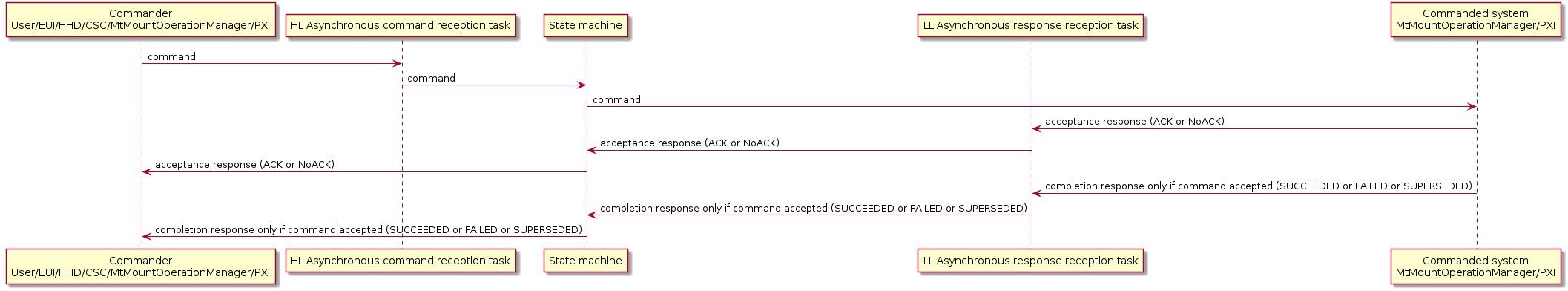
For commanding the CAR (Command Action Response) communication scheme has been adopted. The communication between the programs has been implemented using TCP/IP connections. Therefore, the following kinds of tasks are required in the programs at each level:
High Level (HL) Asynchronous command reception task. This task is in charge of receiving commands asynchronously from the higher level program(s) or from the operator. Whenever a command is received, an event (thread synchronization event) is set for the state machine task. Typical objects used in multithreaded applications (like mutexes) are used to share the data structure associated to the command with the state machine task. One task of this kind is required for each program at the higher level because blocking functions may be used for reading.
State machine task. This task is an active object (event dispatcher and state machine manager) that processes the events (thread synchronization events) set by the High Level Asynchronous command reception task(s) and the Low Level Asynchronous message reception task(s). This task sends the commands to the lower level program(s) and the response messages (Ack, Done, Error, etc) to the higher level program(s). It can also send other notification events (state changes, etc) to the higher level program(s). This task only executes Run To Completion (RTC) actions.
Low Level (LL) Asynchronous message reception task. This task is in charge of receiving messages asynchronously from the lower level program(s). One task of this kind is required for each program at the lower level because blocking functions are used for reading. Depending on the received message, two different actions are possible:
If these messages are responses (Ack, Done, Error, etc) to previously sent commands or asynchronous messages that are relevant for the state machine task, an event (thread synchronization event) is set for this task
If these messages are asynchronous events that are not relevant for the state machine task, they simply are transmitted to higher levels programs.
For monitoring only one kind of task is required in each program. This task receives telemetry data from the lower level program(s) and writes them to the higher level program(s). These variables are sent using a custom TCP/IP protocol from the PXIs that generate the telemetry in a hierarchical process up to the EUI where it’s processed and sent to the CSC. The EUI has the extra functionality of logging the read variables to a file for local data storage.
MCC SW Programs
In the MCC there are two programs (EUI and MtMountOperationManager), the main functions of these two are:
Interface with the operator by means of the Engineering User Interface (EUI):
Commanding. Commanding the TMA.
Monitoring. Display the TMA information (topics and events) received from the Subsystem control program to the operator and log it locally.
Interface with the CSC by means of the MtMountOperationManager and EUI:
Commanding. Allow commanding the TMA from the CSC, uses the MtMount Operation Manager.
Monitoring. Send the TMA information (topics and events) received from the Subsystem control program to the CSC.
Events are received from the MtMount Operation Manager.
Telemetry topics are received from the EUI.
The MtMount Operation management task manages the commands (received either from the EUI, HHD or CSC) and processes the responses received from the PXIs as shown in the diagram from the SW Structure section. There are three High Level Asynchronous command reception tasks, one for attending the commands requested by the operator through the EUI (button pressing, etc), another equivalent for HHD, and a last one for receiving the commands from the CSC. And two Low Level Asynchronous response reception tasks for received the responses for the two PXIs commanded by the operation manager.
The EUI functions are to implement the Engineering user interface, store the telemetry data locally and send the telemetry data to the CSC by the use of the telemetry topics defined in a configuration file. For the user commands available, the user interface (EUI/HHD) uses the approach defined in SW Structure section.
HHD SW Programs
The main functions of the programs running in the HHD are:
Interface with the operator by means of the Engineering User Interface:
Commanding. Commanding the TMA.
Monitoring. Display the TMA information (topics and events) received from the Subsystem control program to the operator.
The HHD functions are to implement the Engineering user interface. For the user commands available, the user interface (HHD) uses the approach defined in SW Structure section. The version of the user interface running in the HHD is lighter than the one on the MCC, as the functions required are less and the hardware is less powerful. Therefore some task are executed less frequently and the screen data is updated less frequently too.
PXI Subsystem Control Program
The main functions of this program are:
Commanding. Execute the commands received from the MtMountOperationManager by controlling the operation of all subsystems of the TMA. The commands supported by the axes subsystems are based in the PLCOpen standard.
Monitoring. Send the telemetry data from the TMA collected from all TMA sensors to the EUI and HHD.
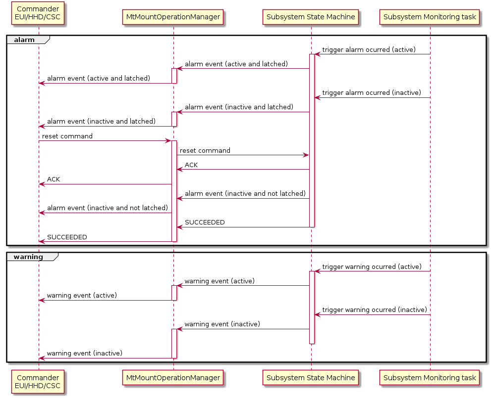
Supervision. Supervise the correct operation of all systems. For doing this, each subsystem has its own task that checks the status of all the variables relevant for the subsystem to detect any possible malfunctions and errors. If a malfunction is detected a trigger is sent to the subsystem state machine task. The state machine task manages the trigger, and depending of the malfunction level, it transits to fault state, sending the event information as a fault event, or maintain the current state and inform of the malfunction by sending the event information as a warning event.
The design pattern explained in SW Structure section is not applied to this program in such a simple way as to the other programs because controlling all the TMA subsystems requires some additional tasks that make the structural design of this program more complex. However, as explained in the following paragraphs, the main ideas explained in SW Structure section are also applied to this program whenever possible.
The subsystems of the TMA and the functions for each of them are listed and explained below:
Azimuth axis main functions:
Axis operation and control. For this function there are several subfunctions required:
Azimuth state machine task. Executed in the TMA-PXI.
Trajectory generation. A custom trajectory generation library has been developed. Executed in the AXES-PXI.
Axis interface. Using the ethercat communications to the main drives and monitoring the status. Executed in the AXES-PXI.
Encoder system interface. Using a two tasks:
Configuration task. Executed in the TMA-PXI.
Data UDP reception task. Executed in the AXES-PXI.
Azimuth Cable Wrap control. Executed in the TMA-PXI.
Elevation axis main functions:
Axis operation and control. For this function there are several subfunctions required:
Azimuth state machine task. Executed in the TMA-PXI.
Trajectory generation. A custom trajectory generation library has been developed. Executed in the AXES-PXI.
Axis interface. Using the ethercat communications to the main drives and monitoring the status. Executed in the AXES-PXI.
Encoder system interface. Using a two tasks:
Configuration task. Executed in the TMA-PXI.
Data UDP reception task. Executed in the AXES-PXI.
Locking pins control. Executed in the TMA-PXI.
Balancing control. Executed in the TMA-PXI.
Mirror Cover control. Executed in the TMA-PXI.
Deployable Platforms control. Executed in the TMA-PXI.
Camera Cable Wrap control. Executed in the TMA-PXI.
TMA IS Interface. Executed in the TMA-PXI.
Cabinet thermal control. Executed in the AUX-PXI.
Drives thermal control. Executed in the AUX-PXI.
TEC control. Executed in the AUX-PXI.
OSS control. Executed in the AUX-PXI.
Main Power Supply control. Executed in the AUX-PXI.
Here, the main functions to be executed by each subsystem and the subfunctions required by each function are listed. The designed program structure is related to this function breakdown. Thus, inside the Subsystem Control Program (Main VI), each TMA subsystem is associated to one VI (Subsystem VI), as well as each subsystem function (Function VI) and each subfunction (Subfunction VI). Inside each Subfunction VI there is at least one loop (one thread). This loop calls as many VIs (subVIs) as necessary to perform the desired operations in each case.
Some of the control functions required to the Subsystem Control Program are performed by intelligent external hardware devices that are commanded and monitored by the Subsystem Control Program using the appropriate communication protocol. Therefore the functionality required to perform these control functions is not implemented in the Subsystem Control Program which only hosts the functions required to communicate with these devices for commanding and monitoring . These devices are:
Bosch controller. This PLC controller is responsible for managing the low level loops of the auxiliary motors used by the following subsystems: Locking Pins, Balancing, Deployable Platforms, Mirror Cover, Camera Cable Wrap and Azimuth Cable Wrap.
Main drives power supply PLC. It manages the DC power supply to azimuth and elevation drives. Connected to the IOs EtherCAT line.
OSS control PLC. It manages the hydrostatic bearings for azimuth and elevation. The communication be via Modbus TCP and it is connected to the Ethernet TMA network.
Main Axes motor section drives. They control the azimuth and elevation motors sections and are connected by EtherCAT.
Cabinet thermal local controllers. They control the surface temperature of the cabinets and allow powering on temperature limited hardware. The communication is done via MODBUS TCP and they are connected to the Ethernet TMA network.
Top End Chiller PLC. It controls the temperature of elements of the top end assembly, as well as the M2 mirror cell assembly. The communication is done via MODBUS TCP it is connected to the Ethernet TMA network.
Similar to other programs forming the MCS, there is a High Level Asynchronous command reception task, for receiving the commands from the MtMountOperationManager via TCP/IP using a custom protocol. For each received command, a trigger to the appropriate state machine for the corresponding subsystem is sent. Once received, the state machine performs the checks for the received command and accepts or rejects the command, if the command is accepted an ACK is sent and if not a reject (NoACK) is sent. If the commands is rejected the command actions end there and the command is cleared. If the command is accepted, the command actions are executed, and when the actions are completed or interrupted a response is sent accordingly as follows:
SUCCEEDED. A command is completed successfully.
FAILED. A command is not completed successfully.
SUPERSEDED. A command is superseded by another one, this happens with the stop commands executed during a move command for example.
This works like this for all the subsystems unless two work as a subsystem for another system. These are the Azimuth Cable Wrap and the Encoder systems, in this subsystems everything works in the same way, the only difference is that the commands do not reach the subsystem directly from the High Level Asynchronous command reception task, they are received from the subsystem(s) on top of them. For the ACW the Azimuth subsystem is the one sending the commands and for the Encoder the commands are sent by both Elevation and Azimuth subsystems.
Monitoring and supervisory task are executed together in the so called monitoring task of the subsystem. This task is the one checking the variables to ensure they are within correct values and if not trigger the state machine to take the pertinent actions, as well as, the one responsible for publishing the telemetry and events corresponding to the subsystem.
The state machines for each subsystem are coded in LabVIEW using a custom framework developed for this purpose, as the originally proposed LabVIEW Statechart Module was giving a bad performance response and was not capable of responding to frequency demands specified in the LTS-103. The developed framework follows the UML specification, as it is based on the LabVIEW Statechart Module.
The following diagram shows the CAR implementation for the PXIs.
![@startuml
node "Mount Control computer" as mcc {
component "MtMount Operation Manager (C++)" as cpp
}
node "TMA-PXI" as tmaPxi {
component "HL Asynchronous command reception task" as tmaReceptor
component "Azimuth\nState Machine & Monitoring Loop" as Azimuth {
component "Azimuth Cable Wrap\nState Machine & Monitoring Loop" as acw
}
component "Elevation\nState Machine & Monitoring Loop" as Elevation
component "Encoder\nState Machine & Monitoring Loop" as encoder
component "Locking Pins\nState Machine & Monitoring Loop" as lp
component "Mirror Cover\nState Machine & Monitoring Loop" as mc
component "Balancing\nState Machine & Monitoring Loop" as bal
component "Deployable Platforms\nState Machine & Monitoring Loop" as dp
component "Camera Cable Wrap\nState Machine & Monitoring Loop" as ccw
component "TMA IS Interface" as safety
}
node "AUX-PXI" as auxPxi {
component "HL Asynchronous command reception task" as auxReceptor
component "Cabinet Thermal control\nState Machine & Monitoring Loop" as cabinet
component "Drives thermal control\nState Machine & Monitoring Loop" as thermalDrives
component "TEC\nState Machine & Monitoring Loop" as TEC
component "OSS\nState Machine & Monitoring Loop" as OSS
component "Main Power Supply\nState Machine & Monitoring Loop" as mps
}
node "AXES-PXI" as axesPxi {
component "HL Asynchronous command reception task" as axesReceptor
component "Azimuth Axis interface" as azInter
component "Elevation Axis interface" as elInter
component "Encoder UDP data reception" as udp
component "Azimuth trajectory generation" as azTraject
component "Elevation trajectory generation" as elTraject
}
node DrivesEtherCAT
node BoschController
node "TMA IS" as pilz
node "IOs and Power Supply EtherCAT" as IOsEtherCAT
node "TEC Controller" as TECdevice
node "Oil Supply System" as OSSdevice
node "Modbus Cabinet Controller" as modbusController
cpp -[bold,#blue]----> tmaReceptor
cpp -[bold,#blue]----> auxReceptor
encoder <-[bold,#green]---> Azimuth
encoder <-[bold,#green]---> Elevation
tmaReceptor -[bold,#blue]----> Azimuth
tmaReceptor -[bold,#blue]----> Elevation
tmaReceptor -[bold,#blue]----> lp
tmaReceptor -[bold,#blue]----> mc
tmaReceptor -[bold,#blue]----> bal
tmaReceptor -[bold,#blue]----> dp
tmaReceptor -[bold,#blue]----> ccw
tmaReceptor -[bold,#blue]----> safety
auxReceptor -[bold,#blue]---> cabinet
auxReceptor -[bold,#blue]---> thermalDrives
auxReceptor -[bold,#blue]---> TEC
auxReceptor -[bold,#blue]---> OSS
auxReceptor -[bold,#blue]---> mps
Azimuth -[bold,#blue]----> axesReceptor
Elevation -[bold,#blue]----> axesReceptor
axesReceptor -[bold,#blue]---> azInter
axesReceptor -[bold,#blue]---> elInter
axesReceptor -[bold,#blue]-> udp
azInter <-[bold,#green]-> azTraject
elInter <-[bold,#green]-> elTraject
thermalDrives -[bold,#red]----> cpp
Azimuth -[bold,#red]----> cpp
Elevation -[bold,#red]----> cpp
lp -[bold,#red]----> cpp
mc -[bold,#red]----> cpp
bal -[bold,#red]----> cpp
dp -[bold,#red]----> cpp
ccw -[bold,#red]----> cpp
safety -[bold,#red]----> cpp
cabinet -[bold,#red]----> cpp
TEC -[bold,#red]----> cpp
OSS -[bold,#red]----> cpp
mps -[bold,#red]----> cpp
udp -[bold,#grey]--> azInter
udp -[bold,#grey]--> elInter
udp -[bold,#red]-> encoder
azInter -[bold,#red]--> Azimuth
elInter -[bold,#red]--> Elevation
encoder -[bold,#blue]-> axesReceptor
DrivesEtherCAT <-[bold,#grey]--> azInter
DrivesEtherCAT <-[bold,#grey]--> elInter
BoschController <-[bold,#grey]--> dp
BoschController <-[bold,#grey]--> lp
BoschController <-[bold,#grey]--> bal
BoschController <-[bold,#grey]--> mc
BoschController <-[bold,#grey]--> ccw
BoschController <-[bold,#grey]--> acw
pilz <-[bold,#grey]--> safety
IOsEtherCAT <-[bold,#grey]-> thermalDrives
IOsEtherCAT <-[bold,#grey]-> mps
TECdevice <-[bold,#grey]---> TEC
OSSdevice <-[bold,#grey]---> OSS
modbusController <-[bold,#grey]---> cabinet
legend right
| **Color** | **Type** |
| <#blue> | commands |
| <#red> | responses |
| <#grey> | data |
| <#green> | commands and responses |
endlegend
@enduml](../../_images/plantuml-3da7ca32bc20a8abf555e887ea40e739c7ed89d4.png)
CAR Implementation
Each subsystem subscribes itself to the command reception task, when this is done the commands allowed for that subsystem are specified. This way when a command is received the command reception task knows to which subsystem is directed. Once the commanded subsystem is defined by the command reception task, the appropriate trigger is sent to the subsystem. This is done using dynamic dispatch, having one parent class with the method trigger statechart and one child for each subsystem with the specific actions for each subsystem. These actions consist on triggering the state machine of the subsystem by defining the corresponding trigger for the received command and adding it to the queue from the state machine task. In subsystems with multiple instances of the state machine, the command receptor decides which one is triggered based on the first parameter from the command, that acts as an index value for the initialized instances array.
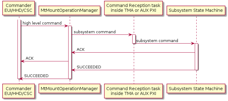
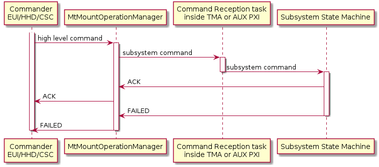
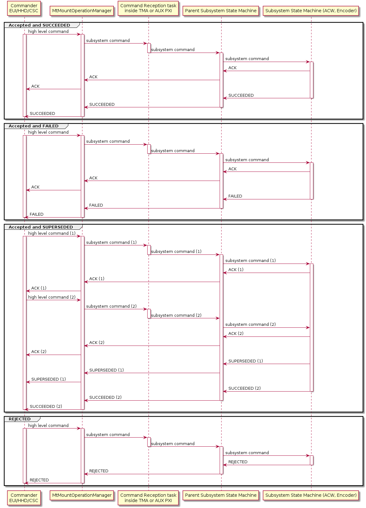
Once the state machine is triggered, the actions coded for the received command are executed. First, the command is evaluated to see if the requested action can be executed. For doing this the command and its parameters are evaluated. If the command is evaluated positively an ACK is sent and the command is executed. If the command is evaluated negatively a REJECTED is sent and the command is not executed. When a command is accepted, the actions defined for that command are executed and then the corresponding response is sent when done. If these actions are completed correctly a SUCCEEDED is sent. If these actions are not completed or are completed with errors, a FAILED is sent with a brief explanation of what happened. If these actions are interrupted by another command, a STOP command for example, a SUPERSEDED is sent specifying which command caused this response.
All the command and responses mentioned above are sent from/to the MtMountOperationManager through TCP/IP, where the PXI acts as a server and the MtMountOperationManager acts as a client. That’s why the MtMountOperationManager has two connections open at any time, to connect to the two PXIs it has to send commands to and receive the responses from each of them.
In addition to the commands and responses, there are events sent from the PXI to the MtMountOperationManager that inform
of the status of the system. These events are sent to the commanders connected to the MtMountOperationManager:
EUI, HHD or CSC. These events are defined in the PXI documentation repo
inside the CommandsAndEventsManagement directory 04 Events.md, from this list the most relevant ones are two:
Warning event. This event informs of an unusual situation but that allows operations to keep going. This event contains the following information:
Name of the warning.
An identifier for the subsystem where the event ocurred.
The name of the subsystem instance where the event ocurred.
Boolean value of the event status, active or not.
Warning code, identifying code number of the warning.
Description of the warning.
Alarm event. This event informs of a bad situation that does not allow operations to keep going. This event contains the following information:
Name of the alarm.
An identifier for the subsystem where the event ocurred.
The name of the subsystem instance where the event ocurred.
Boolean value of the event status, active or not.
Boolean value of the latched status, latched or not.
Alarm code, identifying code number of the alarm.
Description of the alarm.
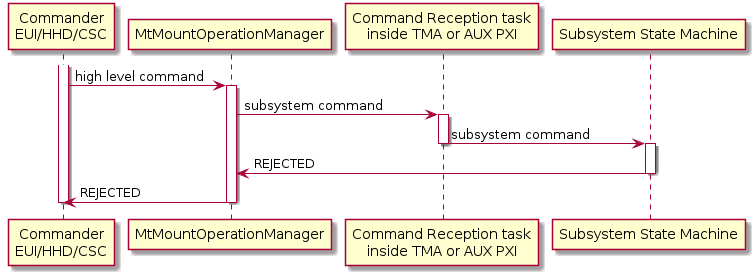
The following diagrams represent the steps for sending a command to a subsystem.
Accepted and SUCCEEDED command.
Accepted and FAILED command.
Accepted and SUPERSEDED command.
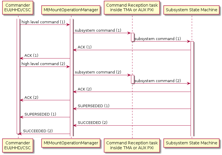
REJECTED command.
Commands for a subsystem that is contained in another (ACW is commanded by Azimuth and Encoder is commanded by Azimuth and Elevation).
Reject from the MtMountOperationManager, the reasons could be a late response from the PXI or not having a connection to the PXI.
![@startuml
participant "Commander\nEUI/HHD/CSC" as commander
participant MtMountOperationManager
participant "Command Reception task\ninside TMA or AUX PXI" as commandReceptor
participant "Subsystem State Machine" as subsystem
group NoConnectionAvailable
commander -> MtMountOperationManager: high level command
activate commander
activate MtMountOperationManager
commander -[hidden]-> MtMountOperationManager: reduce compactness
MtMountOperationManager -> commander: REJECTED
deactivate MtMountOperationManager
deactivate commander
end
group LateACK
commander -> MtMountOperationManager: high level command
activate commander
activate MtMountOperationManager
MtMountOperationManager -> subsystem: subsystem command
hnote over MtMountOperationManager: Too much time without response
MtMountOperationManager -> commander: REJECTED
deactivate MtMountOperationManager
deactivate commander
MtMountOperationManager <- subsystem !!: ACK / REJECTED
end
@enduml](../../_images/plantuml-bd2e38230885c63809ff7f53928cc20a2fa4b2b7.png)
Monitoring task for warning and alarm events.