Bosch Rexroth Recovery
Requested by: |
GHESA |
|---|---|
Doc. Code |
– |
Editor: |
Alberto Izpizua |
Approved by: |
Julen García |
Minor changes by: |
JSeron |
Introduction
This document shows how to recover the Bosch system.
Diagnosis of the Issue
We detect one or more of the following issues:
Cannot power on or control any of the Bosh systems: Azimuth Cable Wrap (ACW), Camera Cable Wrap (CCW), Locking Pins (LP), Mirror Covers (MC), Deployable platforms (DP).
ACW issue
Fault in Azimuth (Az) including STO.
In the Safety System window there is a triggered interlock for the ACW limit (lim+ or lim-).
In ACW window, the position difference between Az and ACW exceeds 3 deg, which is physically impossible by design, as the Az drags the ACW when it reaches its hardware limit.
Making a ping to the Bosch controller (139.229.171.23) faults.
No connection with the Indraworks Engineering Tool (installed on Tekniker’s remote support computer). This is typically a symptom.
Note this tool should only be used in critical cases.
Fatal error (F9XXXX) detected in the Bosh controller located inside the TMA-CBT-CS-AZ-0001 cabinet.
Solving the issue
To resolve the issue, follow these steps, detailed in the subsections below:
Reboot the controller by performing a power-off/power-on sequence.
Clear any existing errors.
IF there is an actual position value issue, resolve it.
Align the ACW with AZ in the TMA EUI.
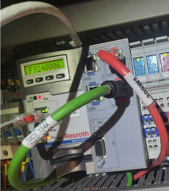
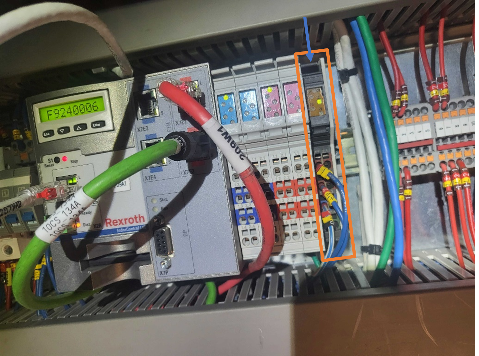
1. Reboot the Bosch Controller
Remove and reinsert the module indicated in the figure in the orange rectangle:
Press the flange on top of the module indicated with the blue arrow
Remove the module. The control light will turn off
Wait for a few seconds
Reinsert the module to power the controller back on
Wait for the system to reboot (this may take a few seconds)
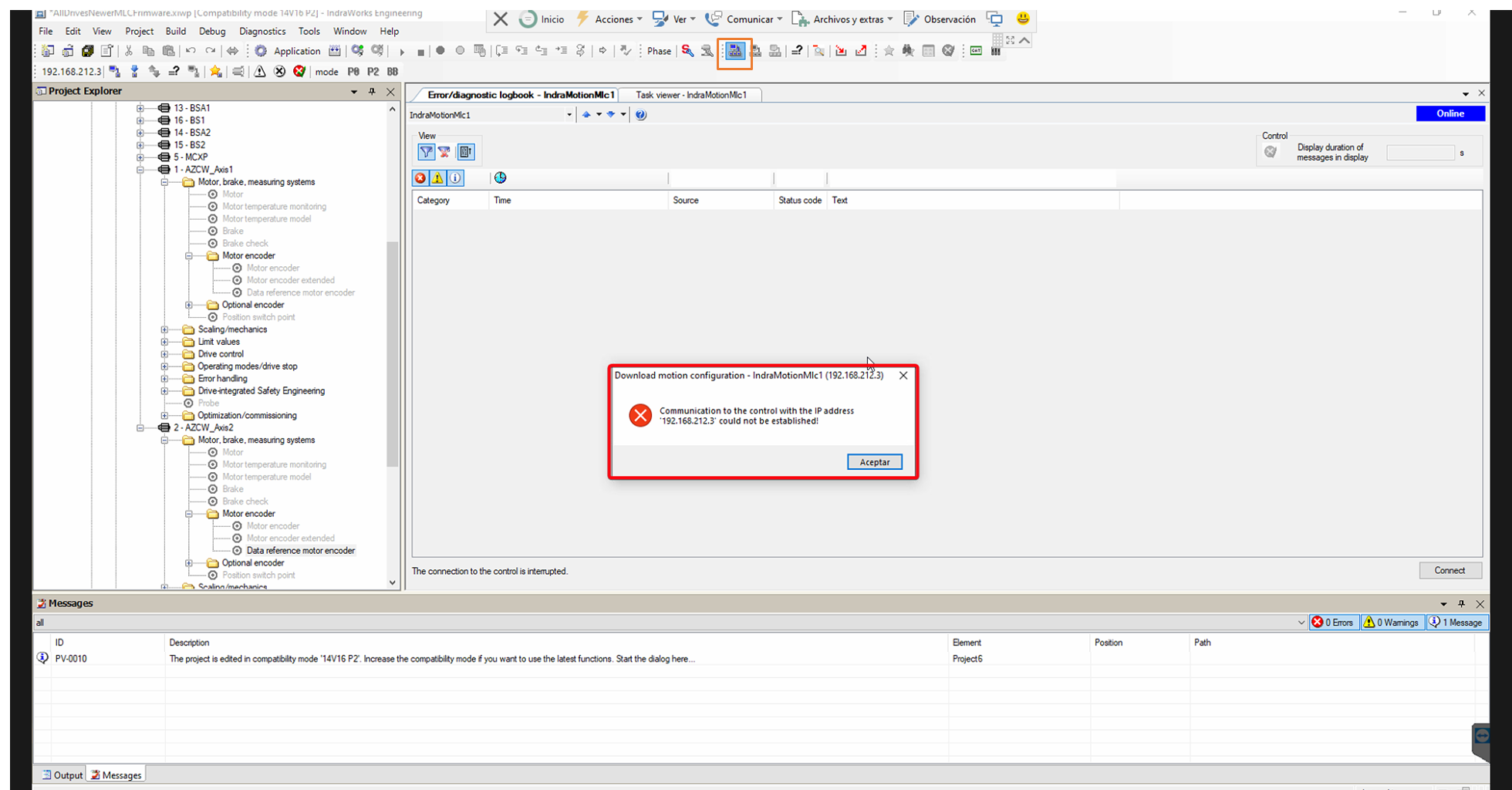
Open the Indraworks Engineering Tool, you may see sync telegram failures errors
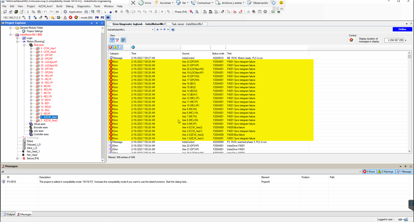
2. Clear errors
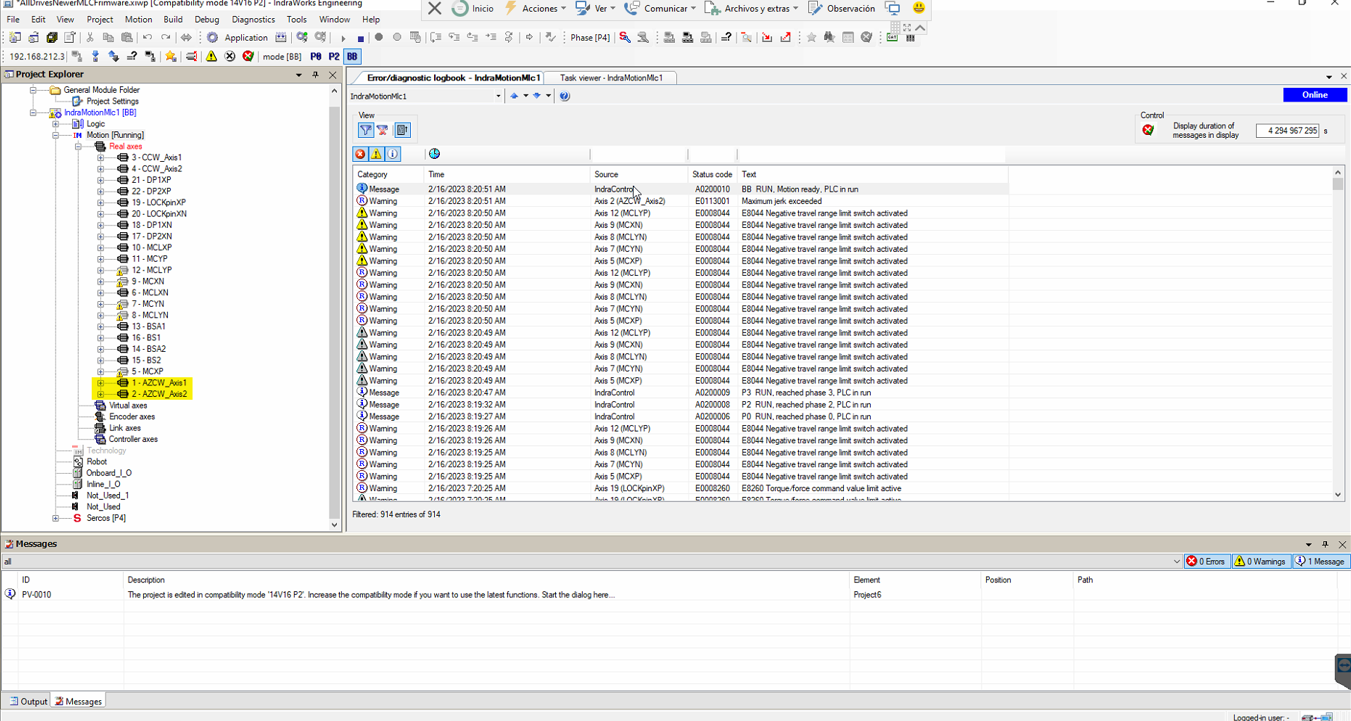
Clear sync telegram failures errors by switching the modes to P0 and BB:
Press the
P0button, to switch to P0 modeWait a few seconds until the status shows P0 to the left of the button
Press the
BBbutton to switch to BB mode and restore communication (this may take up to a minute)
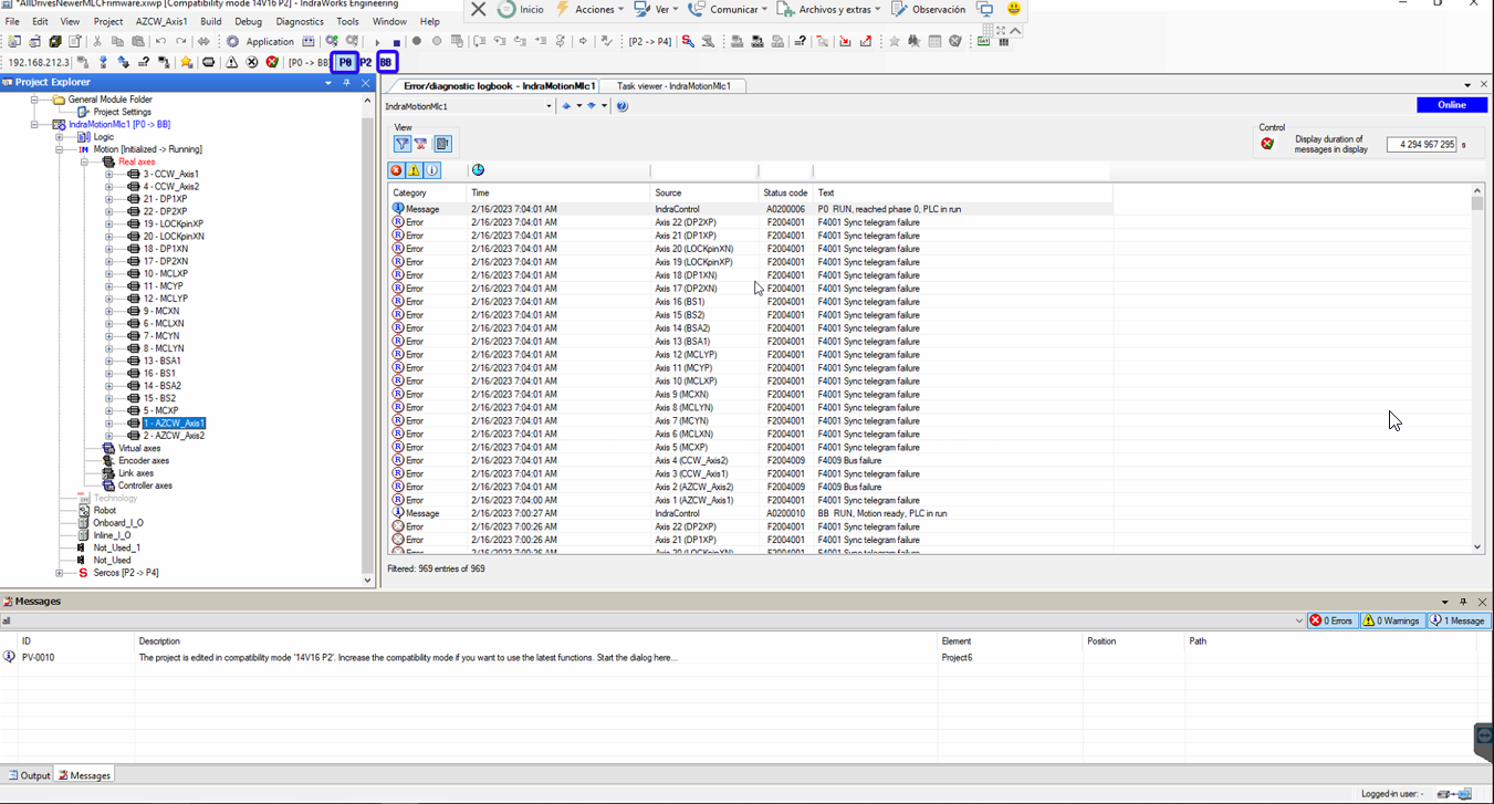
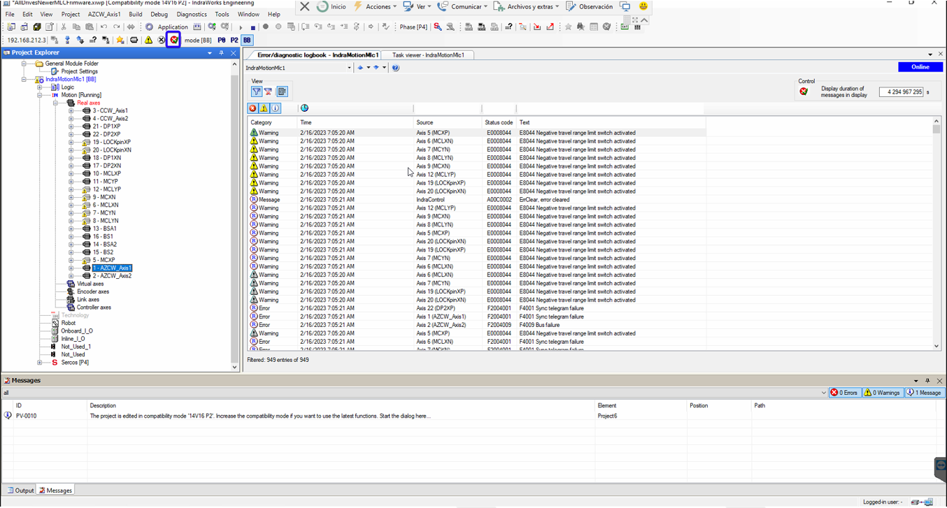
Clear remaining errors with the clear button
3. Case: Issue with actual position value
Execute this step IF AND ONLY IF BOTH of the following conditions are met:
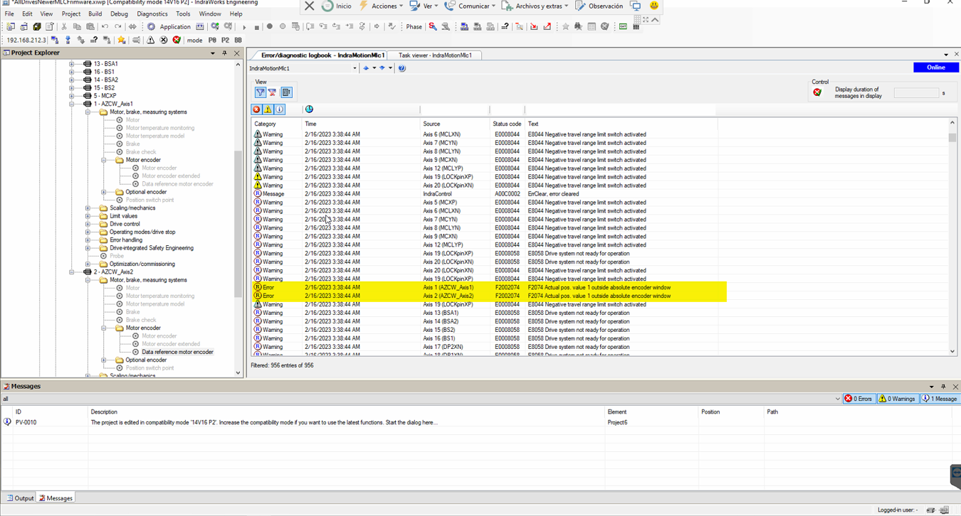
The log shows an error like: “Actual pos. value 1 outside absolute encoder window.“
The ACW motors are in fault (red)
Solving the issue with the actual position value
⚠ WARNING ⚠ Only proceed if you fully understand the procedure as some of these steps are delicate and could be causing further issues if not performed correctly.
In the Indraworks Engineering Tool, open AZCW motor in use, e.g. AZCW_Axis1
Open the page “Data reference motor encoder”

In the “Data reference motor encoder” tab
Check the
Current actual position(1, in the figure) is within ±3.5 deg the actual Azimuth position + 360 Deg. For example, if Azimuth is at 10 deg, the current actual position should be between 6.5 and 13.5 deg.If the position is OK then copy the value in field (1) to
Reference distance(2).Click in
Clear position status(3).Click
Set absolute position(4).
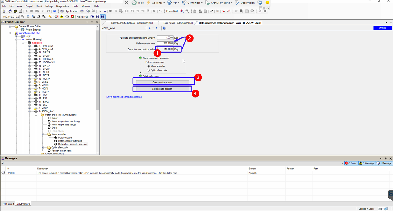
Figure: Data reference motor encoder tab. In this case, the Current actual position is 513. If the TMA Az is between 149.5 and 156.5 degrees, copy the current actual value (513) to the Reference distance field, then press buttons labelled as 3 and 4. .
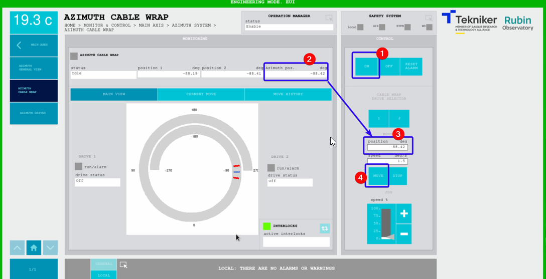
4. Align ACW with Az - in the TMA EUI
Set Azimuth axis to idle state
Go to Azimuth Cable Wrap window
Turn on ACW motor
Copy the actual Az position
Paste it to the position field
Move ACW
Turn off ACW motor
Go to the Safety System
Reset the ACW issue
Continue with operations