ATS Deployment
Code |
Editor |
|---|---|
3151_MCS_0051 |
Julen Garcia |
Introduction
This document describes the procedure to setup the different systems for running the automatic test system.
Software Deployment
Each hardware has different software parts, and some hardware had more than one software part. In the following sections each hardware element is explained.
Windows Machine
In the Windows Machine some simulators and some tools are running.
Force EtherCAT Variables DEPRECATED
This tool allows writing data to EtherCAT variables to other simulators using a TCP based custom protocol. The value written using this tool will overwrite any set value, so any slave value will be overwritten with the written value. The source code and more documentation about configuration can be found in this repo
Follow next steps to deploy this software:
If the installer is available continue to step 6
Clone the repository in the link above
Open the project
ForceEtherCATVars.lvprojGo to Build Specifications and right click in ForceIOs to select Build
Go to Build Specifications and right click in ForceEtherCatVars Installer to select Build
When compilation is finished, open location and copy the
Volumefolder to Windows MachineInstall the tool using the install.exe
Run ForceIOs.exe.
BoschPowerSupplySimulator
This is a simulator for the bosch power supply, this simulator manages the digital inputs that tell the TMA PXI the status of the power supply. The source code and more documentation about configuration can be found in this repo
Follow next steps to deploy this software:
If the installer or executable is available continue to step 6
Clone the repository in the link above
Open the project
BoschPowerSupplySimulator.lvprojGo to Build Specifications and right click in Executable to select Build
When build finishes go to build folder and copy all files and folder
Paste compilation files to desired destination in Windows Machine
Run BoschPowerSupplySimulator.exe
motorThermalModelSimulator
This is a simulator for the thermal behavior of the phase motors, this simulator manages the analog inputs that tell the TMA PXI the temperatures of the motors and uses this values to control the output signal of the valve to manage the temperature of them. The source code and more documentation about configuration can be found in this repo
Follow next steps to deploy this software:
If the installer or executable is available continue to step 6
Clone the repository in the link above
Open the project
motorThermalModelSimulator.lvprojGo to Build Specifications and right click in Executable to select Build
When build finishes go to build folder and copy all files and folder
Paste compilation files to desired destination in Windows Machine
Run motorThermalModelSimulator.exe
PhasePowerSupplySimulator
This is a simulator for the phase power supply, this simulator manages the analog inputs that tell the TMA PXI the status of the power supply. The source code and more documentation about configuration can be found in this repo
Follow next steps to deploy this software:
If the installer or executable is available continue to step 6
Clone the repository in the link above
Open the project
PhasePowerSupplySimulator.lvprojGo to Build Specifications and right click in Executable to select Build
When build finishes go to build folder and copy all files and folder
Paste compilation files to desired destination in Windows Machine
Run PhasePowerSupplySimulator.exe
Simulate limits
This software allows to simulate the behavior of some subsystem limits switches. Those limits could be part of safety system or EtherCAT distributed IOs. The source code and more documentation about configuration can be found in this repo
Follow next steps to deploy this software:
If the installer or executable is available continue to step 6
Clone the repository in the link above
Open the project
SimulateLimits.lvprojGo to Build Specifications and right click in “SimulateLimits” to select Build
When build finishes go to build folder and copy all files and folders
Paste compiled files to desired destination in the Windows Machine
Open the
datafolder and openGeneralConfiguration.xmlCheck the IPs for the limits variables
Run SimulateLimits.exe
cabinetTemperatureControllerSimulator
This is a simulator for the temperature controller of the cabinets, this simulator contains the simulator of the different temperature controllers available all over the telescope. The source code and more documentation about configuration can be found in this repo
Follow next steps to deploy this software:
If the installer or executable is available continue to step 6
Clone the repository in the link above
Open the project
cabinetTemperatureControllerSimulator.lvprojGo to Build Specifications and right click in Executable to select Build
When build finishes go to build folder and copy all files and folder
Paste compilation files to desired destination in Windows Machine
Run cabinetTemperatureControllerSimulator.exe
The cabinets included in this simulator are:
TMA_AX_DZ_CBT_0001 (Phase Main Power Cabinet)
TMA_AZ_CS_CBT_0001 (TEK Mount Control System cabinet - MCS)
TMA_AZ_PD_CBT_0001 (Azimuth Power Distribution)
TMA_AZ_PD_TRM_0001 (Isolation transformer)
TMA_EL_PD_CBT_0001 (Elevation Power Distribution 1)
TMA_EL_PD_CBT_0002 (Elevation Power Distribution 2)
extensionSimulatorForDP
This is a simulator for the extensions of the deployable platforms, this simulator manages the digital inputs that tell the Safety system the status of the extensions of the deployable platforms. The source code and more documentation about configuration can be found in this repo
Follow next steps to deploy this software:
If the installer or executable is available continue to step 6
Clone the repository in the link above
Open the project
DPextensionsSimulator.lvprojGo to Build Specifications and right click in Executable to select Build
When build finishes go to build folder and copy all files and folder
Paste compilation files to desired destination in Windows Machine
Run extensionSimulatorForDP.exe
OilSupplySystemSimulator
This is a simulator for the Oil Supply System (OSS), this simulator contains a modbus server that connects to the AUX PXI to transmit the status of the OSS. The source code and more documentation about configuration can be found in this repo
Follow next steps to deploy this software:
If the installer or executable is available continue to step 6
Clone the repository in the link above
Open the project
OilSupplySystemSimulator.lvprojGo to Build Specifications and right click in Executable to select Build
When build finishes go to build folder and copy all files and folder
Paste compilation files to desired destination in Windows Machine
Run OilSupplySystemSimulator.exe
SpeedgoatManager
This is a simulator tool used for the robot framework tests to connect to the Speedgoat. The source code and more documentation can be found in this repo.
Follow next steps to deploy this software:
Get the latest version of the compiled code from built app repo in a folder called
SpeedgoatManagerGet the latest version of the compiled models for the speedgoat and clone the repo in a folder named
slrtbinariesforspeedgoatnext to theSpeedgoatManagerfolder. The result should look like the image below: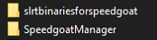
Top End Chiller simulator
This is a simulator for the Top End Chiller (TEC), this simulator contains a modbus server that connects to the AUX PXI to transmit the status of the TEC. The source code and more documentation about configuration can be found in this repo
Follow the steps defined in the repo README
WriteTekNsvVariables
This is a tool to update the required TekNSV variables in the TMA-PXI with a default value or by manually providing one. This is used for setting the status of the deployable extensions as well as the AZ and EL brakes pressures, but more variables can be written by updating the config file of the tool. The source code and more documentation about configuration can be found in this repo.
If the installer or executable is available continue to step 6
Clone the repository in the link above
Open the project
Write TekNSV Variables.lvprojGo to Build Specifications and right click in Executable to select Build
When build finishes go to build folder and copy all files and folder
Paste compilation files to desired destination in Windows Machine
Run WriteTekNsvVariables.exe
Start/Stop the Simulators and Tools in Windows
You can use the scripts in ts_tma_hil_simulators-start-stop-scripts to start or stop all ATS related applications in a once. You need to modify the paths of applications in scripts.
Linux Machine
In the Linux Machine the secondary axis simulators and the robot framework tests are running.
secondaryAxisSil
This is a simulator for the secondary axes (bosch axes), this simulator contains a modbus server that connects to the TMA PXI to transmit the status of each of the axes. The source code and more documentation about configuration can be found in this repo
Follow the steps defined in the repo README
robotFramework
This refers to the automatic test framework the installation steps to setup the environment for robot framework is explained here
The source code and more documentation can be found in this repo
TMA PXI
This is the PXI where the control code for all subsystems is running. To be able to configure the TMA PXI, the development PC should be configured as shown in the deployment document
Download the PXI repository
Open the
ATS_Projects/ATS_LSST_MainControllerPXI.lvprojThis project is only meant to be used for building the TMA PXI code for the ATS
Ensure that in the project properties the Conditional Disable Symbol
HILis set toTrueRight click in the project an select properties
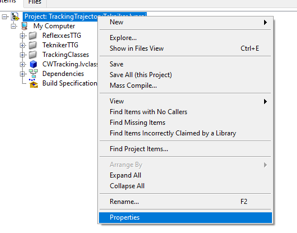
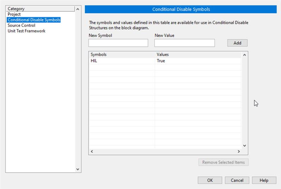
In the opened window go to Conditional Disable Symbols page and set the value for
HILsymbol toTrue.
Open the main
RT_MCS_Main.viSolve the requested dependencies if they appear.
Close the main.
Save all the request files.
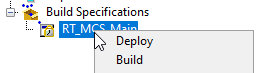
Build the
rtexeOpen the Build Specifications section
Right click and build
Once built, deploy the rtexe to the target. This can be done using SSH (scp) or with the LabVIEW project.
Before rebooting the PXI, deploy the Network Shared Variables (NSVs) for the ATS.
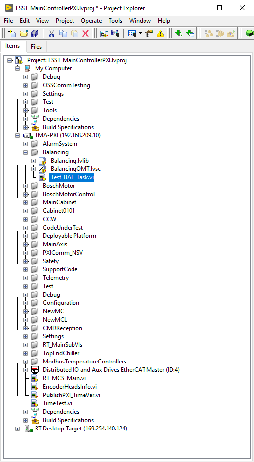
Open the
ATS_Projects/ATS_TMA_PXI.lvprojConnect the project to the PXI
Deploy the
ATS_ECATSlave_NSV.lvlib. This lib contains the NSVs for the ATS simulation mode.
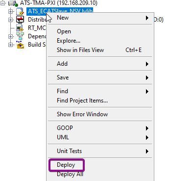
Note that these NSV variables are meant to replace the need for an ethercat master in the TMA PXI for the ATS. Therefore, deploying the ethercat config in this project is not necessary.
Disconnect from the project
Reboot the PXI -> check the boot of the PXI with the labviewmessages alias command
To test just one subsystem some specific test VIs can be found inside the corresponding subsystem folder. For example the Balancing specific test VI shown bellow:
These are not built, but could be run and deployed from the project directly if needed
You need to copy the required .so libraries, setup NTP/PTP, set the cron job, add the configruraion files in /c/Configuration, modify the IPs in the configuration file, and more.
This step applies to the Axes PXI and AUX PXI as well.
See tma-pxi deployment, tma-pxi target, and Deploy On Targets introduction for more details.
For the EIB configuration file (multi_ext.txt), use the multi_extForATS.txt instead and rename it to multi_ext.txt.
You might need to get or update the related IP, port, gateway, and UDP destination (IP, MAC, and port) as well (see changing-eib-ip).
For the UDP destination, it would be the ATS AXES PXI.
To test the EIB connection, you can go to the Encoder system window in the EUI and press power on for AZ or EL, if it comes on, then you are OK, if not, something is wrong.
For the safety configuration files (Safety_ModBusMapping_ForReadWriteDefinition.txt and Safety_ModBusMapping.txt) in /c/Configuration/Safety, use the Safety_ModBusMapping_ForReadWriteDefinition_ForATS.txt and Safety_ModBusMapping_ForATS.txt instead and rename them to Safety_ModBusMapping_ForReadWriteDefinition.txt and Safety_ModBusMapping.txt.
For the Bosch system configuration file, copy the BoschSILConfig.ini file to /c/Configuration directory and modify the IPs inside to point to the VM that runs the ts_tma_hil_secondary-axis_secondaryaxissil.
Since there are many IPs in the configuration files in /c/Configuration directory, it would be good to check the current values on summit or ATS before any modification.
You can do grep -nr "139" /c/Configuration or grep -nr "192" /c/Configuration to check each IP address based on the case that the PXIs are on the summit or ATS.
139.x.x.x belongs to the Rubin IP domain in Chile and 192.x.x.x belongs to the Tekniker IP domain (in case you copy the configuration file from the ts_tma_labview_pxi-controller).
You can use the host command to check each IP address if it has an assigned hostname.
You can also check the current TMA setup here: Ethernet-Connections.
The control system will generate the log file in the /home/lvuser/log directory.
Make sure you create this directory in advance.
The ownership of log directory should be lvuser:ni.
This ownership appies to the /c/Configuration as well.
You can do a soft link of /home/admin/logs to this log directory.
This step applies to the Axes PXI and AUX PXI.
Axes PXI
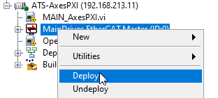
Same as TMA-PXI, but instead of opening the TMA project, open the ATS_Projects/ATS_MainAxes.lvproj and the
MAIN_AxesPXI.vi. And instead of deploying the NSVs library, deploy the ethercat master, see image below.
You might need to download the build cRIO-9145 FPGA bitfile. See ethercat-crio-9145. See note of NI-9145, electrical-connections, and ATS_ElectricalSchematics.pdf for more details.
Copy the MainAxisConfig_forATS.ini to the /c/Configuration in PXI and rename it to be the /c/Configuration/MainAxisConfig.ini.
You may want to check the EtherCAT slaves can be put into the Operational state or not. Connect the ATS_MainAxes.lvproj project to the ATS AXES PXI. Right click the MainDrives EtherCAT Master to see the Online Master State option. Click it and the LabVIEW should pop up a window to show the current 3 slave states:
x2 are the speedgoat modules.
x1 is the cRIO that triggers the EIB signal, note that the EIB is NOT connected to the ethercat line directly. See the details in ATS_HardwareDesign.
If the ATS AXES PXI does not detect the slaves using the Online Master State, check the following:
The speedgoat is up and running.
The ethercat connections are in place and right order, see ethercat-line-device-order.
Note of NI-9145
The cRIO-9145 regularly sends a synchronous signal to the EIB by the NI-9401 module (Mod1/DIO0 and Mod1/DIO1). If the FPGA code in the cRIO-9145 runs correctly, you should be able to see:
The cRIO “FPGA LED” flashs in the running.
In the NI distribution system (you need to add the ATS AXES PXI to it), the CyclesCounter (how many times that the EIB has been triggered) increases overtime. This counts the FPGA executions, so as long as it’s increasing everything should be OK.
The flashing of FPGACodeRunningClock in the NI distribution system. This is a true/false clock that will be constantly switching if the FPGA is running.
If you check the MainFPGA.vi in MainAxesPXI.lvproj, you will see Input Virtual Point is used to trigger a state machine to send the signal to EIB. This is synced to the Ethercat scan engine, and that’s why it is used to trigger the EIB. See more details in ni-9145-timing-diagram. This FPGA code is running while the Ethercat is in Active mode, therefore this signal (Input Virtual Point) is automatically generated by the cRIO. You cannot check it from outside the FPGA code, as it is not exposed to the outside by anything at the moment.
If you check the NI distribution system, you can see the InputVirtualPointTiming to be 1000. This allows people to check the “Input Virtual Point” sampling time, which is in fact an indirect way of measuring the “Input Virtual Point” and see that it is working fine. As a value of 1000 usec = 1ms, the sampling rate of Ethercat.
You can measure the pulse duration from the cRIO to the EIB as well. From the NI distribution system, you can see
WaitTime_ticks = 14600
OnTime_ticks = 6400
FPGA clock = 40 MHz
Digital output ON time in seconds 1/40MHz * 6400 = 0.00016 seconds (0.16 ms). Therefore, it is recommended to use the oscilloscope to check this synchronous signal when needed.
AUX PXI
Same as TMA-PXI, but instead of opening the TMA project, open the ATS_Projects/ATS_AuxSystemsController.lvproj and the
AuxSystemsMain.vi. For this PXI there are no libraries to be deployed
For the CPU temperature monitor task to work, the ssh key generation is required.
See (ssh-keys-for-cpu-temperatures)[https://ts-tma.lsst.io/docs/tma_pxi-controller_documentation/80 DeployOnTargets/02 AUX PXI.html#ssh-keys-for-cpu-temperatures].
Make sure you have tested the lvuser in AUX PXI can ssh to the TMA PXI and AXES PXI.
You need to put the public key to the /home/admin/.ssh/authorized_keys for the above two PXIs.
You might need to modify /c/Configuration/CpuTempMonitoring/PxiCpuMonitoringConfiguration.json for the path of temp1_input file.
It could be /sys/devices/platform/coretemp.0/hwmon/hwmon0/temp1_input, /sys/devices/platform/coretemp.0/hwmon/hwmon1/temp1_input, or others, which depends on your PXI controller.
For the Modbus temperature controller configuration files, copy the ModbusTemperatureControllers directory to /c/Configuration directory and modify the IPs and ports in ini files to point to the VM that runs the ts_tma_hil_cabinet-temperature-controller_cabinets.
You also need to remove the _forATS word in the file name.
For example, rename the TMA_AX_DZ_CBT_0001_mapping_forATS.txt to TMA_AX_DZ_CBT_0001_mapping.txt.
For the top-end chiller, the configuration files are in the TEC.
Note that for the ATS, you need to modify the Address and Port in ServerConfig.ini.
The Port value is assigned in main.py of ts_tma_hil_simulator_top-end-chiller.
For the oil supply system, the configuration files are in the OSS.
Note that for the ATS, you need to modify the Address and Port in ServerConfig.ini.
The Port value is assigned in OSS_ServerConfig.ini of ts_tma_hil_oil-supply-system_oil-supply-system-simulator.
For the ATS AUX PXI, if it is a Beckhoff device as aux-pxi, you can configure it to be a PXI by following: after-installation-to-set-as-pxi. Note you might need to use the following two commands instead for the instructions on the above link:
grub-editenv - set DeviceDesc=PXIe-8880_Beckhoff
grub-editenv - set hostname=ats_AUX-PXI
Safety code deployment
The code that runs on the PILZ controller to simulate the behavior of the TMA IS. The source code and more documentation about configuration can be found in this repo
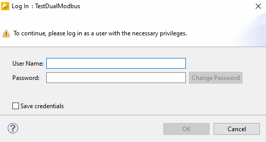
Open the TestDualModbus project with PAS4000 version 1.18.0
Activate the TestDualModbus
Open the online network editor.
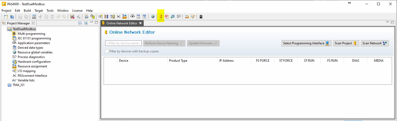
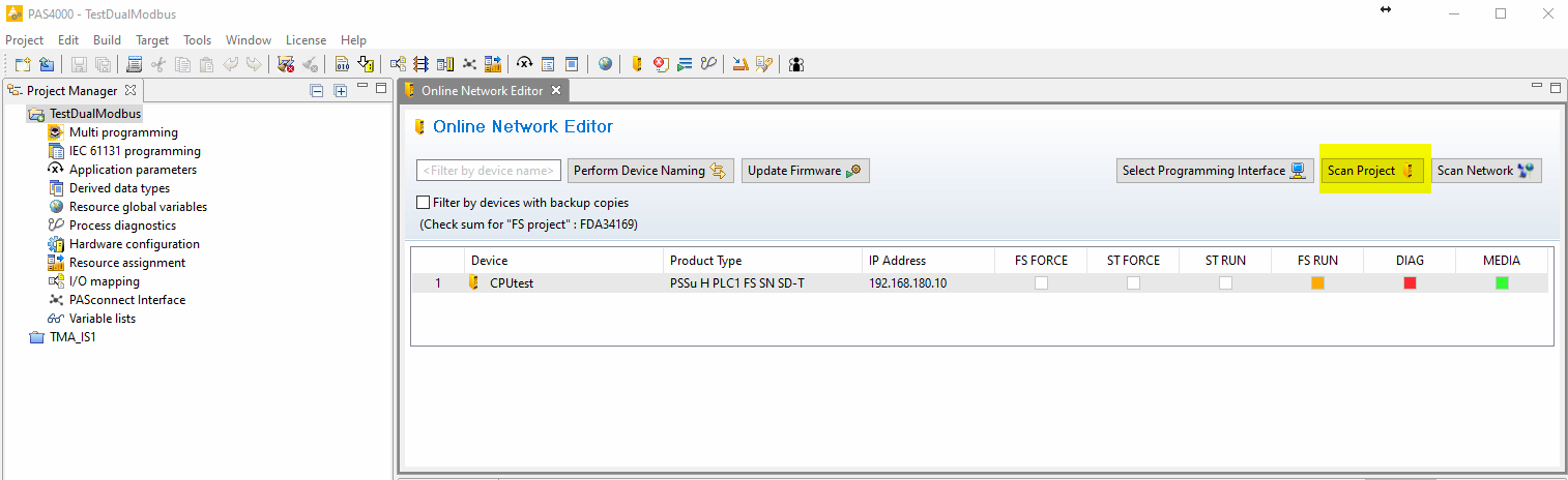
Scan project to scan the network to verify that the PILZ CPU is connected.
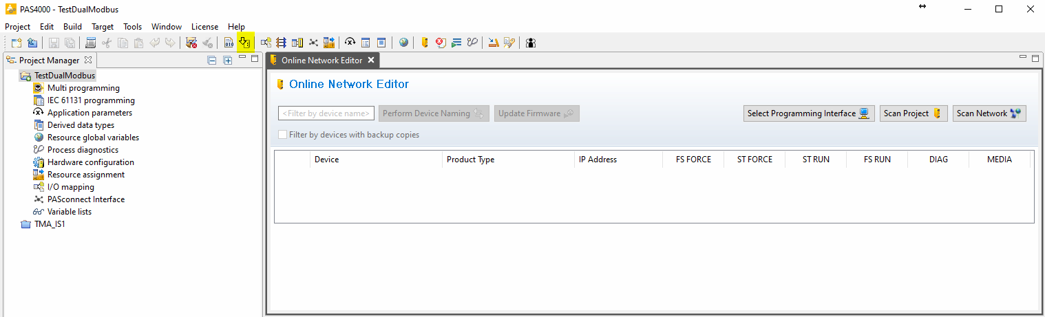
Close the online network editor
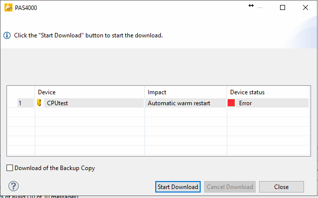
Download the project
Open the Project downloader:
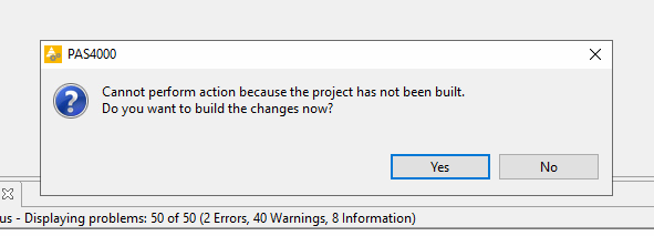
If asked to build changes say YES
Start download:
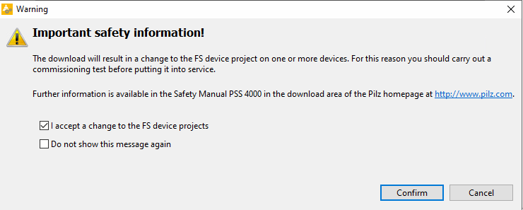
Confirm download:
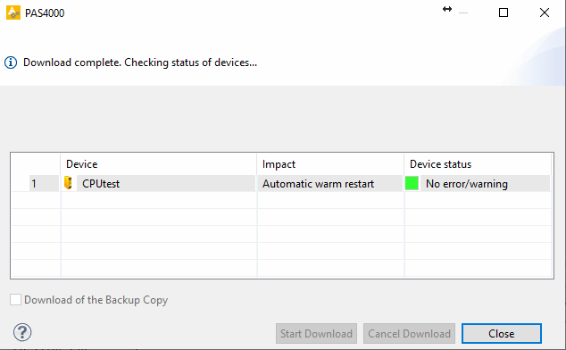
Download completed:
Logout:
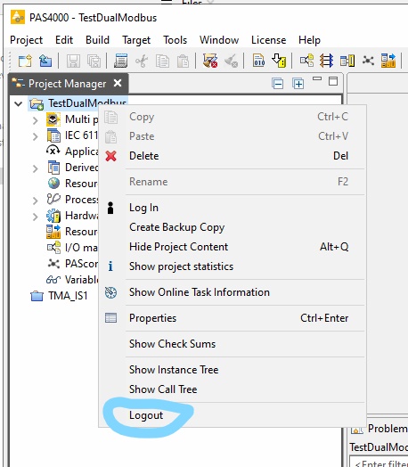
Close the PAS4000
Relevant considerations and miscellaneous
Database
When setting up the ATS is important to have a separated database instance just for the ATS system, the backups for these can be found here.
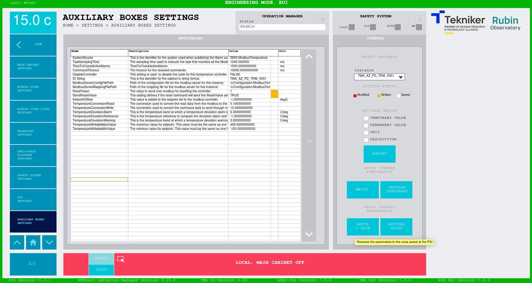
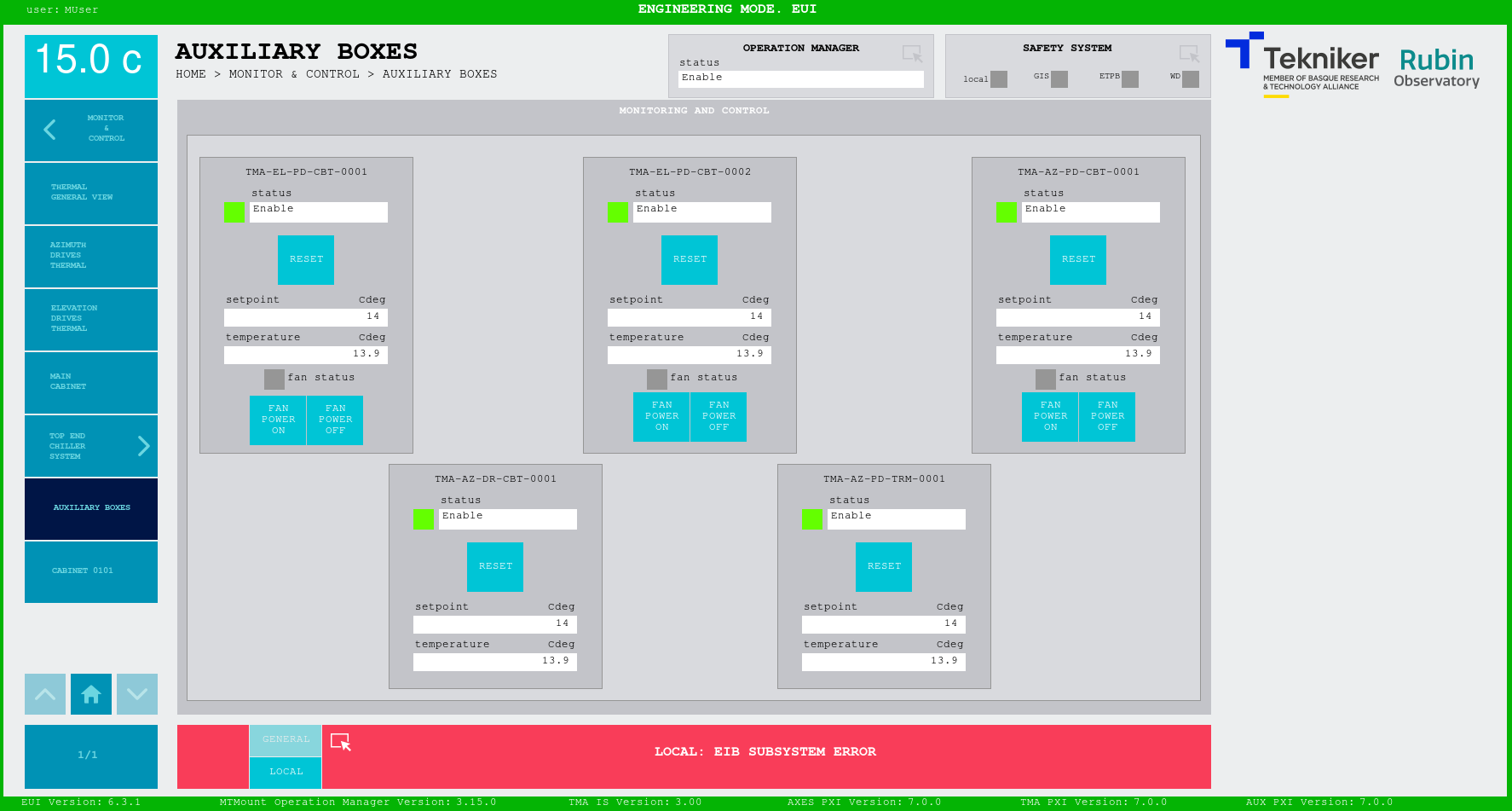
Cabinet modbus temperature controllers
For the auxiliary cabinets temperature controllers the Send reset and Reset value settings are updated to TRUE and
1 respectively, to act as a power on when sending the reset command. This means that each time the cabinets simulators
is booted, the cabinets temperature controllers would be off, until a reset command is sent to each of them.
This is done with the
ManualResetvariable from the PXI which for the ATS is pointing to the1016register of the simulators, the power register.
Elevation inclinometer
The default value for the elevation inclinometer variable TMA-EL-CS-CBT-0101-220A30_ElevationInclinometer is set to
10430 which means a position of 45.22500002 deg. This is done to have a valid EL position when powering on the EL
axis, this variable is not updated by any simulator, but it can be manually updated.
EUI
The executable of the EUI for the ATS and the TMA are the same, the only difference is that the database, the PXIs and the operation manager it targets must be different. This is why the ATS must use a different instance of the EUI than the real TMA, for this we recommend using a different machine. The EUI can be installed from a RPM package found here