ATS Hardware Design
Code |
Editor |
|---|---|
3151_MCS_0050 |
Julen Garcia |
Introduction
This document explains the hardware configuration used for the automatic test system (ATS).
Hardware configuration
In this section the needed hardware and its configuration is explained.
Windows Machine
This is a Windows 10 machine where LabVIEW simulators and tools run.
The configuration of the hardware is:
CPU: Intel i5-7500 @ 3.40GHz
RAM: 8 GB
Hard Drive: SSD 250 GB
OS: Windows 10 Pro version 1909
x2 Ethernet gigabit connection ports
Speedgoat
The Speedgoat is a real time target machine used to simulate the main axes behavior.
The configuration of the hardware is:
CPU: Intel i7-7700K @ 4.20GHz
RAM: 4 GB
Hard Drive: SSD 500 GB
Required Input/Output modules:
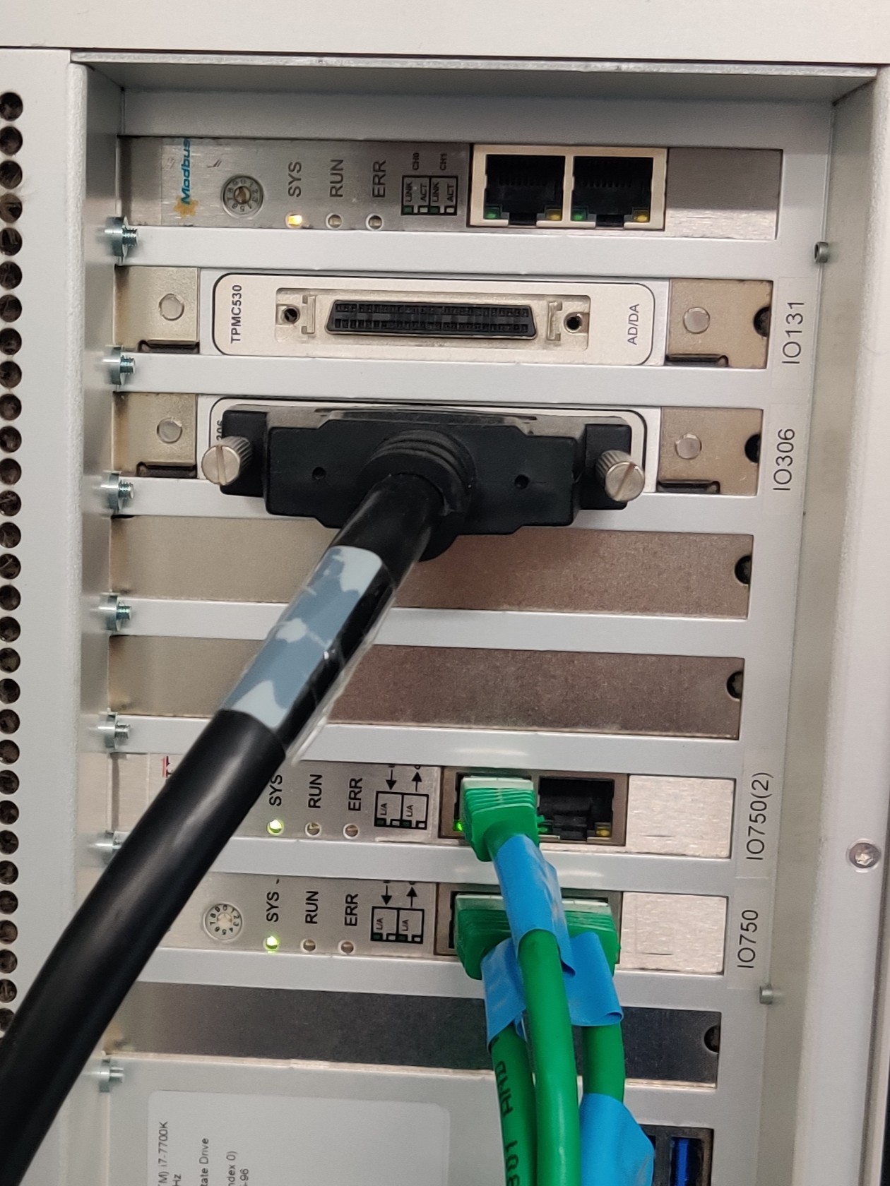
Ethercat Slave module IO750 (x2)
Digital IOs module IO306
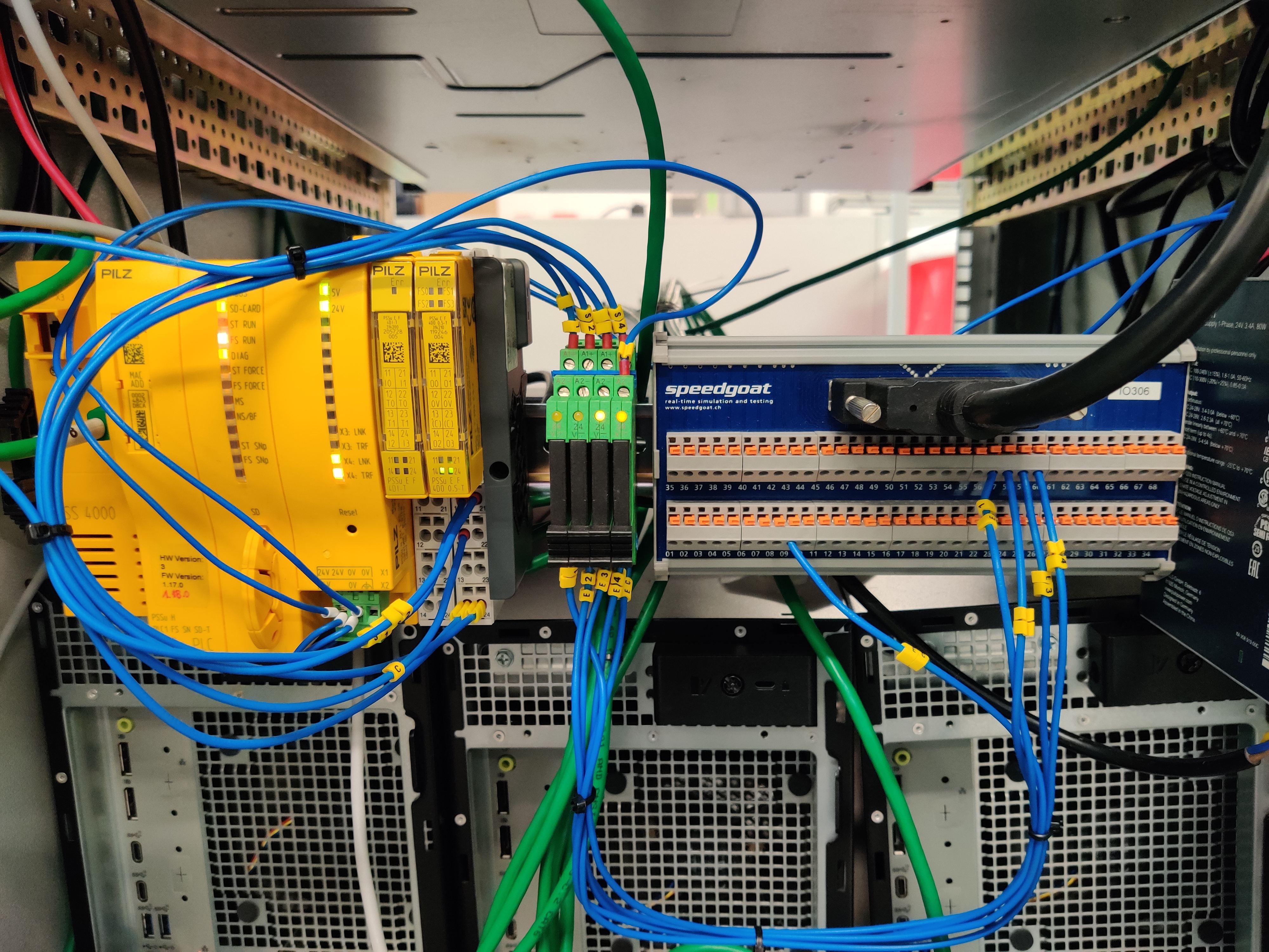
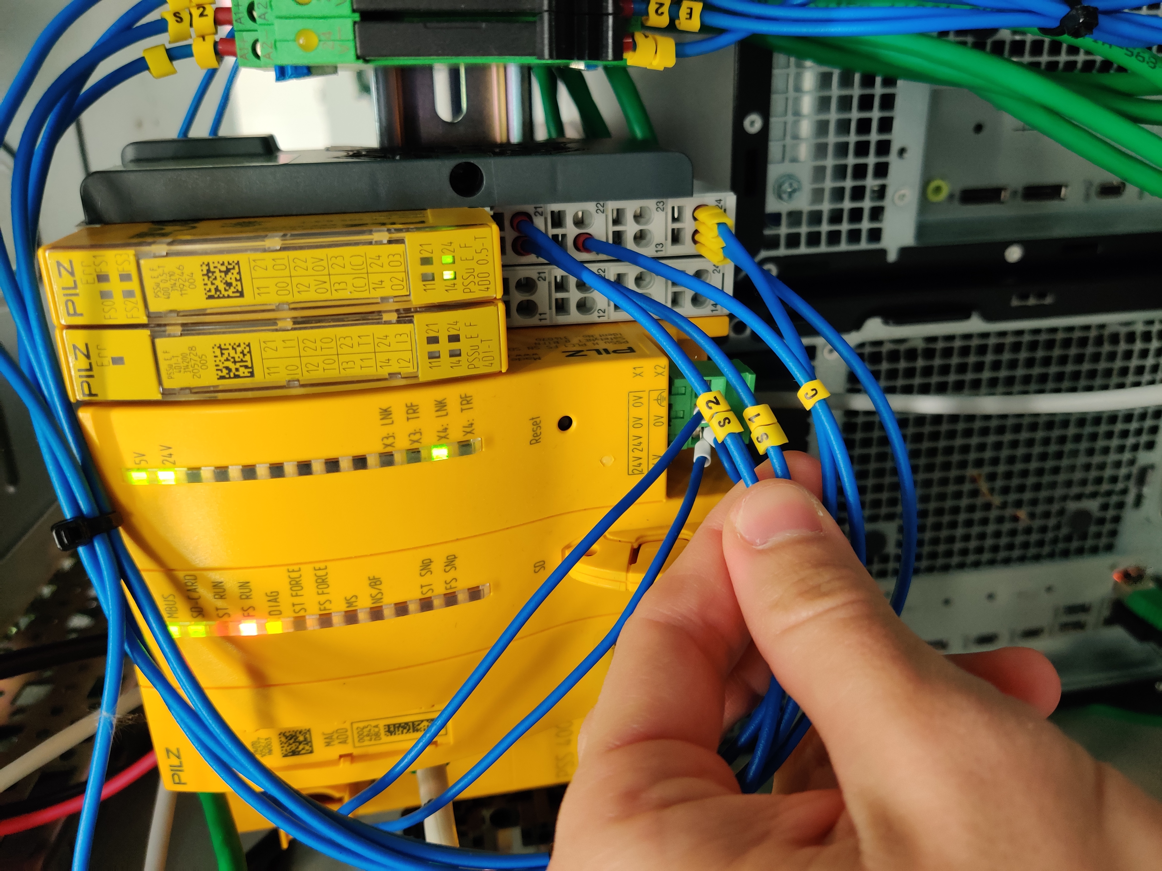
PILZ CPU
This is used to simulate and test the safety software.
The configuration of the hardware is:
PILZ PSSu 4000 ref 314070
PSSu E F 4DI-T (not really in use at the moment)
PSSu E F 4DO 0.5-T
Linux VMs
There are two Debian 12 VMs for the ATS.
ATS Bosch Dockers
For running the secondary axis (bosch axis) simulators in docker containers, no graphical interface installed.
This has the following software installed:
xe-guest-utilities -> for status reporting to the hypervisor
git
docker-ce docker-ce-cli containerd.io docker-buildx-plugin docker-compose-plugin
vim
VM hardware config:
x4 cores
4 GB RAM
80 GB ROM
ATS Run Tests
For running the robot framework tests.
This has the following software installed:
xe-guest-utilities -> for status reporting to the hypervisor
git
vim
Python 3.11.2
requirements from here
KDE Plasma for graphical interface
Remote desktop for running the tests
VM hardware config:
x12 cores
16 GB RAM
80 GB ROM
Mount Control Computer (MCC)
This is a CentOS 7 machine which replicates the one in the server room at the summit in Chile. It runs the EUI (Engineering User Interface), the database for the settings and events and the mtmount_operation_manager.
The configuration of the hardware is:
CPU: Intel i7-3770 @ 3.40 GHz
RAM: 16 GB
Hard Drive: HHD 500 GB
OS: CentOS 7
x2 Ethernet gigabit connection ports
Tekniker local and internet network
PXIs subnet
The configuration of the hardware for a ALMA9 OS version is:
Non-NI hardware: DELL Precision 3660
CPU: Intel i7-12700
RAM: 16 GB
Hard Drive: NVME 250 GB
TMA PXI
The PXI that contains the state machines for all the main systems and the communication with the MCC and AXES PXI.
The configuration of the hardware is:
Non-NI hardware: DELL Precision 3660
CPU: Intel i7-12700
RAM: 16 GB
Hard Drive: NVME 250 GB
AXES PXI
The PXI that contains the code for controlling the main axes, azimuth and elevation.
The configuration of the hardware is:
Non-NI hardware: DELL Precision 3660
CPU: Intel i7-12700
RAM: 16 GB
Hard Drive: NVME 250 GB
AUX PXI
The PXI that contains the code for the temperature controllers and the OSS state machines.
The configuration of the hardware is:
Non-NI hardware: DELL Precision 3660
CPU: Intel i7-12700
RAM: 16 GB
Hard Drive: NVME 250 GB
EIB 8791
The EIB is the encoder system used to monitor the heads of azimuth and elevation, same as in the summit, more info here
cRIO NI 9145
This cRIO + 8 DIO Module NI 9401 are used to trigger the EIB, same as in the summit, more info here
Ethernet Switches and Connections
The setup in Tekniker uses 2 switches, a managed one and an unmanaged one.
Managed Switch
Netgear GS724Tv4 ProSafe 24-port Gigabit Ethernet Smart Switch. Managed switch ports and VLAN configuration:
Ports |
VLAN |
|---|---|
1 - 6 |
209 |
7 - 8 |
213 |
9 - 12 |
211 |
13 - 14 |
180 |
This is the main switch where the following items are connected:
MCC (VLAN 209: for HMI data communication)
TMA PXI (VLAN 209: for HMI data communication)
TMA PXI (VLAN 213: for communication between the two PXIs)
TMA PXI (VLAN 211: for communication with the EIB)
AXES PXI (VLAN 213: for communication between the two PXIs)
AXES PXI (VLAN 211: for communication with the EIB)
EIB (VLAN 211: for communication with the EIB)
VLAN 209
VLAN 213
VLAN 211
VLAN 180
Switch config
Unmanaged Switch
D-Link DGS-1024D 24 ports Gigabit Ethernet Switch for local network access, this connects to the local network in Tekniker.
Electrical connections
The setup for the ATS is very simple compared to the real one, but there are a couple of connections anyway.
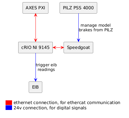
Ethercat line device order
AXES PXI -> cRIO 9145 -> Speedgoat IO750 -> Speedgoat IO750(2)
Digital signals
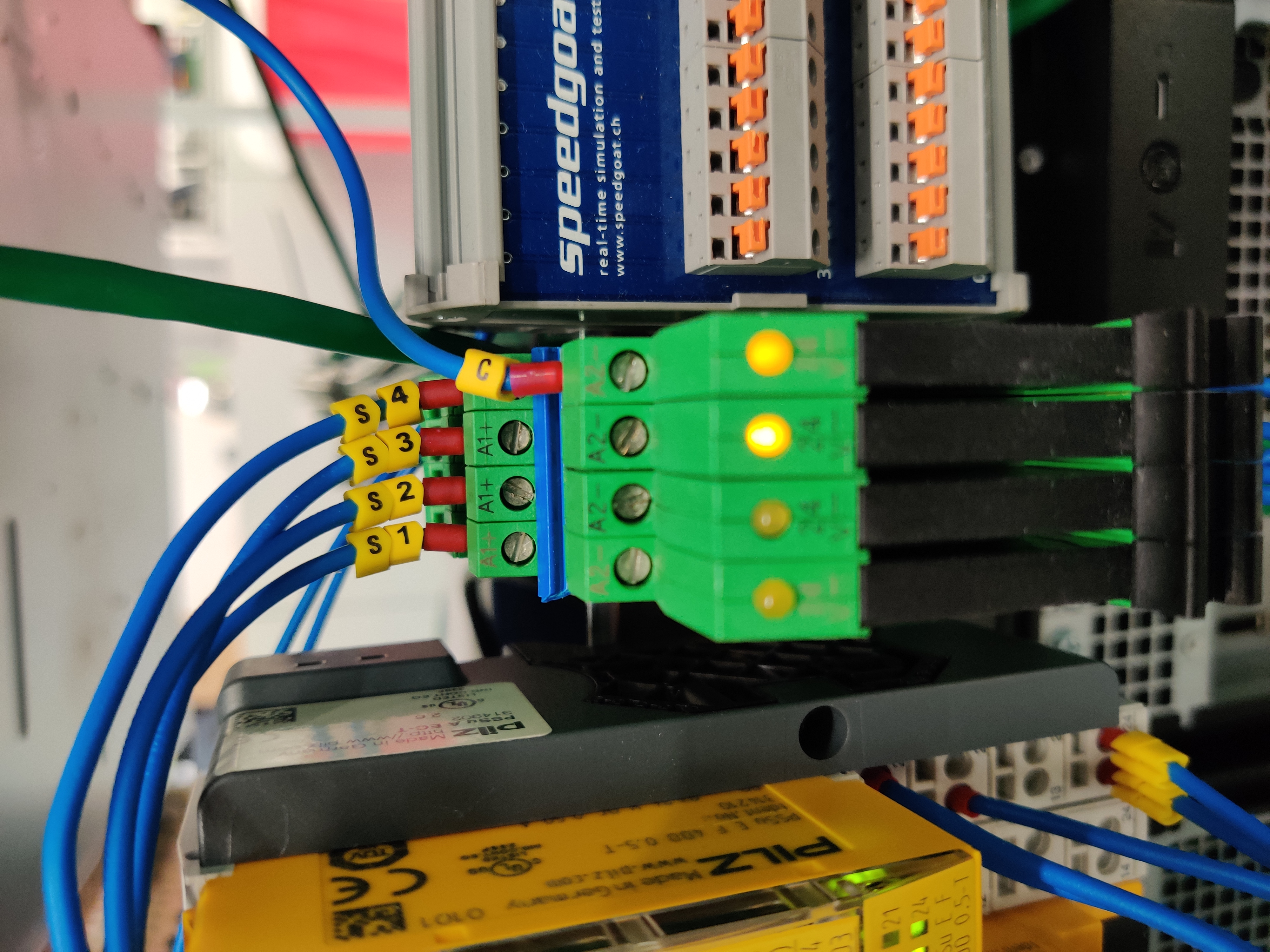
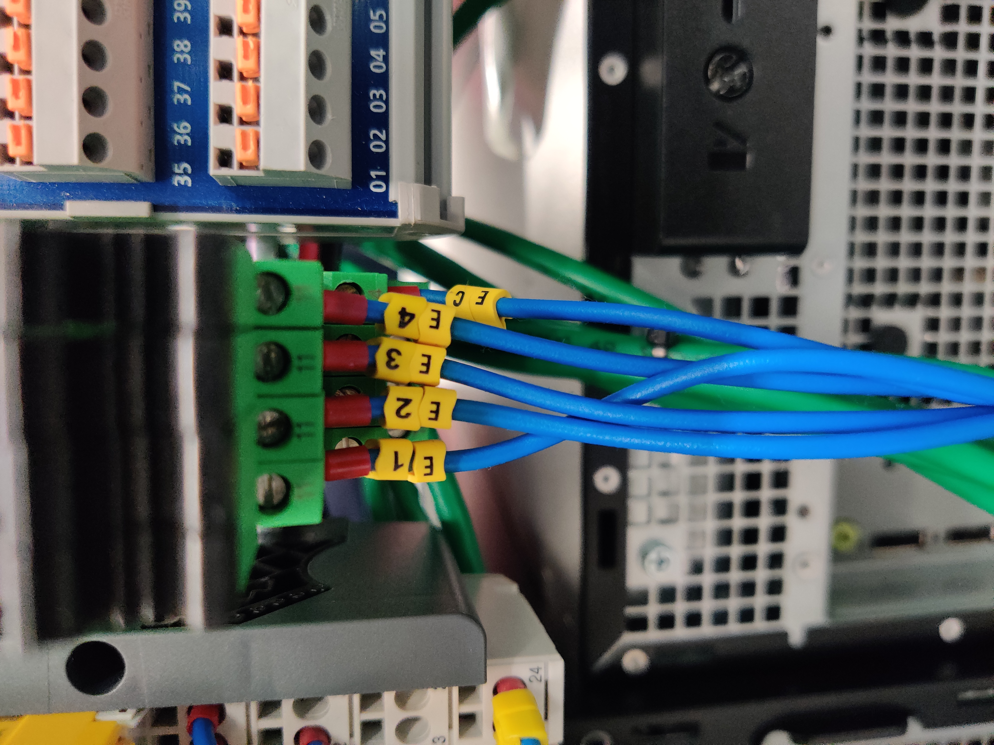
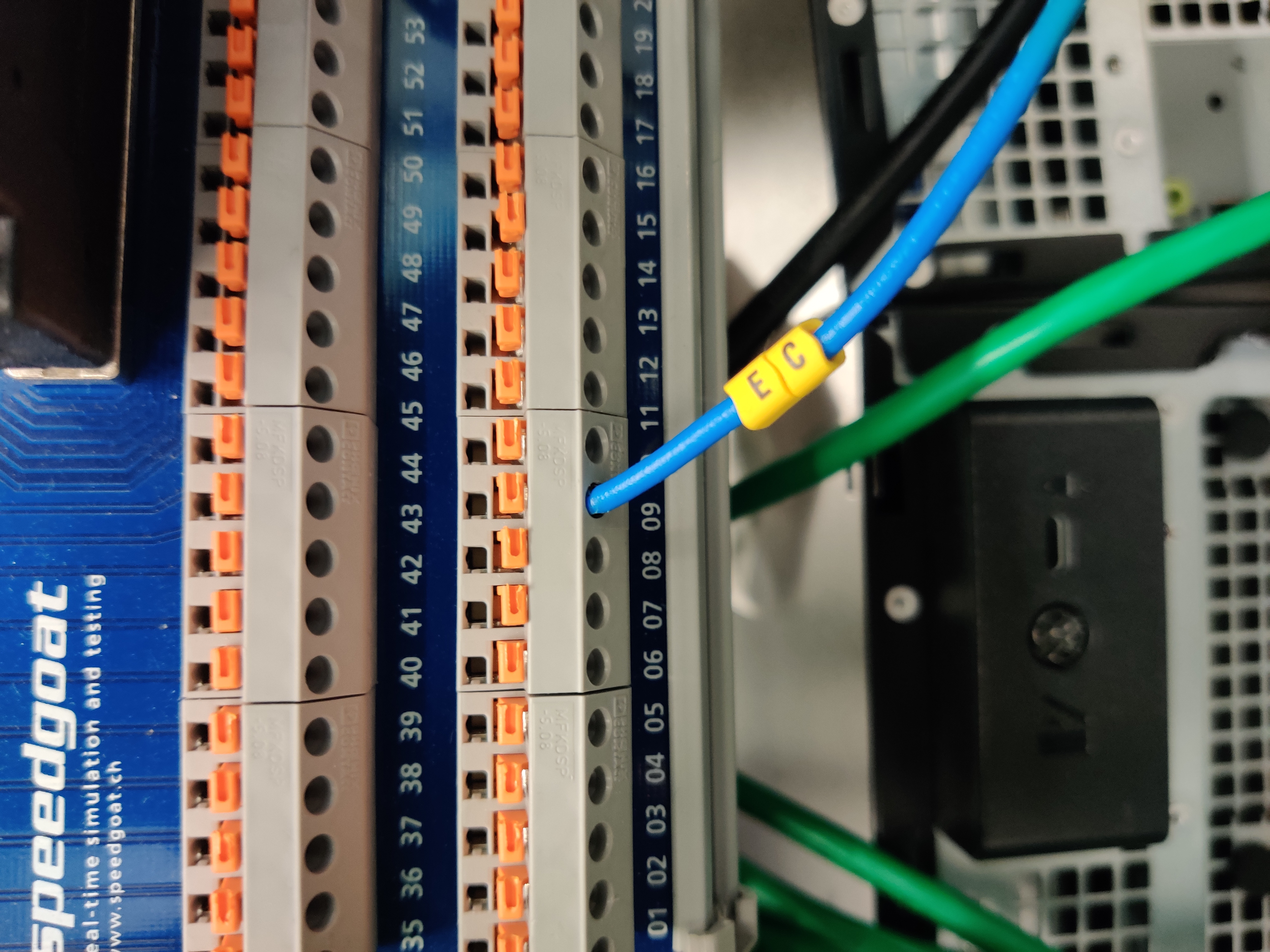
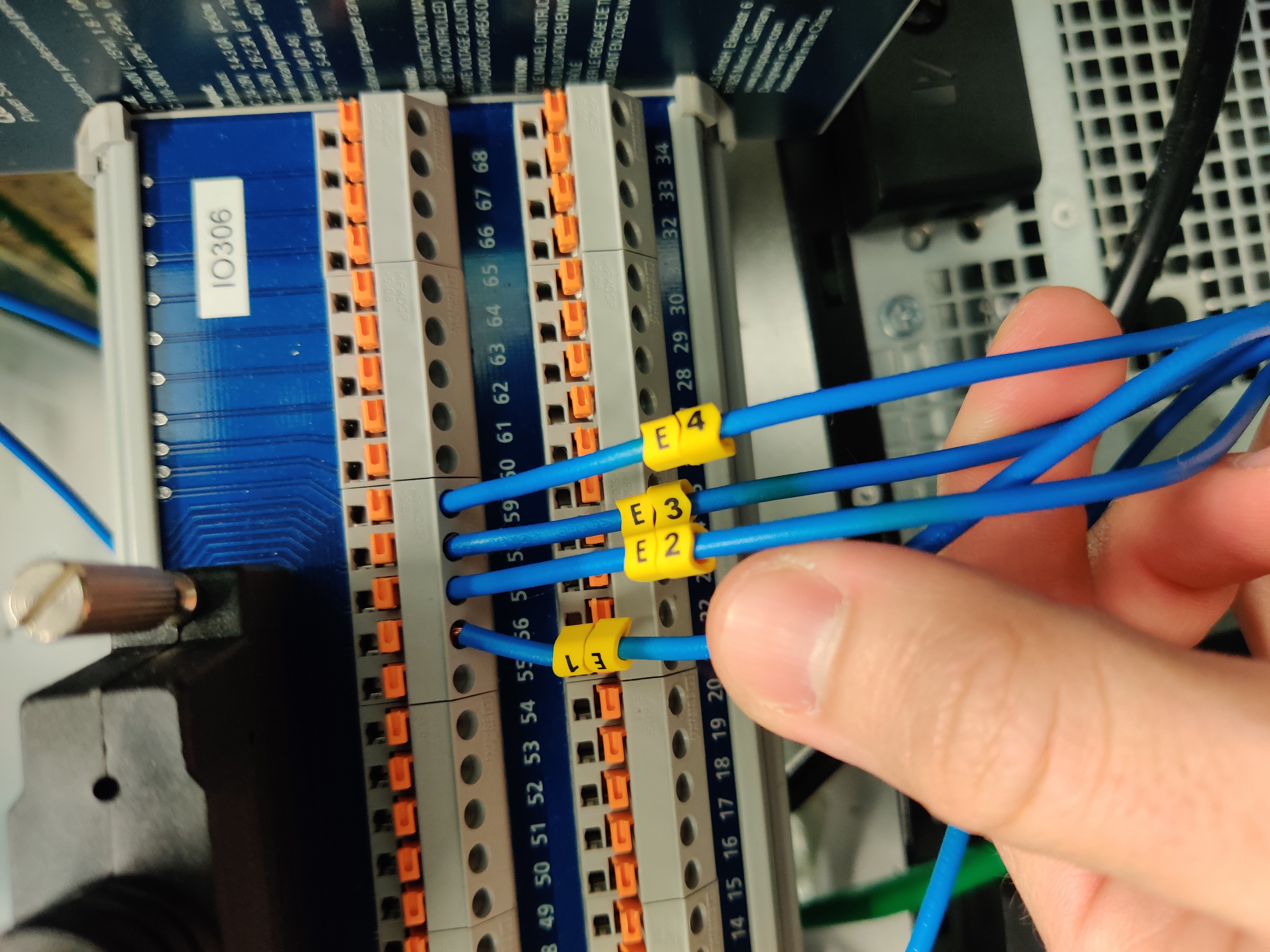
Speedgoat IO306 card -> module with the 24V signals from the PILZ
Hardware configuration at Tekniker
Speedgoat modules
Pilz And Speedgoat Connections