2023 - Training September-October (HW + SW)
Hardware
Hardware slides can be found here
The aim of this section is locating and explaining main hardware elements in the telescope.
Main hardware elements:
OSS
Location
Purpose:
Pressurized oil supply (bearings and brake oil supply)
Additional:
Distributed control cabinets with temperature control (we provide just the setpoint)
How does it works from EUI, and what it can and can’t do
Pier cabinet
Location
Explain the elements that are wired here
All the fixed elements below AZ (not rotating)
ACW
Location
How it works and what it can do.
HW Limits and location
How to get out of the HW limits
What to check if the position of the ACW is very wrong for some reason
Fix: power on AZ, do home, and the system will fail when ACW will try to go to the “wrong” position
Capacitor bank cabinets (Not Tekniker, limited knowledge)
Location
Capacitor 8 Cabinets
Charging cabinet
Power distribution cabinets
Indicators
Azimuth drives
Explain location and how they work (we provide torque setpoint through ethercat)
Temperature control
Azimuth limit switches and topple block
Location and how they work
Azimuth encoder tape and heads
Explain location and how they work
Wired to EIB
Elevation drives
Explain location and how they work
Temperature control
Elevation encoder tape and heads
Explain location and how they work
Wired to EIB
Elevation limit switches
Location and how they work (all range and operational AZ doesn’t have this)
Main azimuth cabinet (AZ-0001)
Location
Temperature control
Contents:
PXIs
Bosch controller and drives (ACW and CCW), the rest are distributed in the motors
Safety controller, totally independent from the MCS control, main target PROTECT PEOPLE (equipment damage is converted to people damage)
Ethercat devices, two lines:
I/Os
Drives
EIB (there is just 1 for both AZ and EL)
RMC
Ethernet connections
Azimuth cabinet 0101
Location
Temperature control
Contents:
IOs
Safety IOs
Main power supply (Not Tekniker, limited knowledge)
Location
Temperature control
How does it works from EUI, and what it can and can’t do

Locking pins
Location
Use
Limits, which indicate position in the EUI but are also wired to the safety system
Deployable platforms
Location
Use
Limits, which indicate position in the EUI but are also wired to the safety system
How to request permission to extend platforms from the EUI, as the locks are managed by the Safety PLC (PILZ)
Mirror cover (with locks)
Location
Use
Limits, which indicate position in the EUI
Manual disable switch for maintenance
Elevation cabinets inside CST
Location
Contents:
IOs
Safety IOs
Balancing
Location
Use
Limits
Auxiliary boxes (temp control)(Not Tekniker, limited knowledge)
Location
Temperature control
TEC if ready
Location
CCW if ready
Location
Use
Limits, deviation and range limits
Software
Software slides can be found here
Before starting with this section, is important to review these two files:
Hardware Configuration tools
EIB configuration tool
There is some documentation on how to change the IP here useful as a start point.
Bosch configuration tool 3 docs:
Bosch_Controller_Startup_Configuration: This repo contains the document for the startup of the Bosch Controller (MLC) and its configuration.
BoschRexrothRecovery: This repo has the documentation to recover the Bosch Rexroth hardware from a stuck situation or a major fault.
ReplaceBoschMotor: Documentation with procedure to replace a Bosch motor and configure it. In this document there are no mechanical instructions for the replacement.
TwinCAT, for ethercat diagnosis
NI distributed system manager: manages the ethercat from the PXIs, this tool comes from National Instruments and can only run on windows
Check signals from the remote IOs, e.g. that the bosch power supply is on
EZ-Zone Configurator: for the temperature controller in the AZ-0001 cabinet. Backup config file here
Startup+: for the ethercat modules in all 5 cabinets, AZ-0001, AZ-0101, EL-0101, EL-0102 and PI-0001. This configuration must be done locally using a micro usb cable. The backup configuration files are saved here
PAS4000
This is the tool used to code the PILZ safety controllers used in the telescope.
Understanding Safety systems
Safety systems main target is PROTECTING PEOPLE (equipment damage is converted to people damage, as equipment is usually expensive and hard to replace). Is important to notice that safety systems are totally independent from the control devices, as in this project the PXIs that control the TMA are independent from the PILZ safety controllers.
Keeping this in mind, safety systems are designed to reduce human risks with a safety related function. One function for each possible risk obtained from a safety evaluation. The equipment or machine risk can be considered in the analysis but it must be converted to human risk for including it in the safety function.
Classification of severity (Se) [1]
Consequences |
Severity (Se) |
|---|---|
Irreversible: death, losing an eye or arm |
4 |
Irreversible: broken limb(s), losing a finger(s) |
3 |
Reversible: requiring attention from a medical practitioner |
2 |
Reversible: requiring first aid |
1 |
Safety matrix
The code that must be included in the safety controller is defined in the safety matrix. Here the actions for the detected causes are listed. This way, when a cause occurs, the system knows how to react to it in a safe manner.
Using the tool
This tool is used as a PLC development environment, here the best is to familiarize with it in a training course from PILZ. But there are simple things that a user with limited experience can do, e.g. forcing variables, this can be done for example to override an input or output value. Even though this is a simple action, it is not recommended, as forcing variables in a safety controller can lead to serious accidents.
Configuration files
There are multiple configuration files in the TMA.
EUI config files
Modifying these files could affect the performance of the system
The EUI has the following config files:
PXI config files
Modifying these files could affect the performance of the system
Each PXI has a different set of config files, as each PXI runs a different executable. Config files per target:
These files can be modified to change the behavior of the system, for example some systems require and update if the
target IP changes, for example the OSS IP is defined in the AUX PXI inside the /c/OSS/ServerConfig.ini file. It is
also important to keep the names of the files, if changed the corresponding task may not start, this could be a way for
disabling certain subsystem if necessary.
EUI
There is a manual for the EUI available online, both in Spanish and English:
Overall review of the EUI
Explain the interlocks, that affect the power on of the system and are displayed on the bottom right part of most of the subsystem windows. If not the rejected response received when trying to perform the power on will contain the list of the active interlocks that prevent the power, these are displayed as pop ups when a command is sent, see pop ups section.
Historic data display in the EUI, 2 days max
Maintenance or useful commands
Force/unForce ambient temperature in the EUI
Reset allafter reboot to improve performance, as the state machines need to be executed at least once to run properly
Users
How to change from one user to another
Alarms
How to investigate the alarm log and get the relevant information from them
Explain relevant settings for maintenance purposes
Locking pins disable elevation angle check if the position is known, but for some reason doing home in elevation was not possible.
Disable modbus temperature controllers when cabinets disabled e.g. when removing the Camera
Elevation parking, using the predefined setting sets
Mirror cover stuck, disable collision checks, dangerous
Setting sets
Pop ups
There are times when a pop up message appears in the EUI, these pop ups could be software errors in the EUI or messages coming from the PXIs, like rejected messages.
Software errors in the EUI: these are usually due to communication issues with the PXIs, therefore are very common after a PXI reboot, if that is the case they are not relevant. They just mean that the task reading from the PXIs failed and will be launched again.
Messages from the PXIs: these are relevant, as they tell the user meaningful information about the system, they could be:
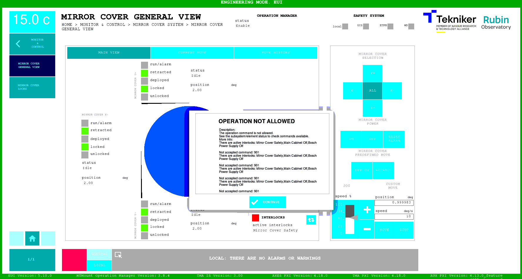
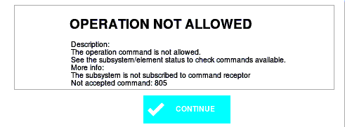
Rejected: these are responses sent when a command request is rejected, for example in the next figure a
power oncommand is rejected for all the mirror covers, here the active interlocks are:Mirror cover safety: there is safety interlock preventing the power on, check the safety matrix in the safety window
Main Cabinet off: the temperature controller for the main cabinet is in critical fault state, it must be reset for enabling the power on
Bosch Power Supply Off: the power supply for the bosch controllers is off, this means that the motor controlled by bosch can’t be powered on.
Timeout acknowledge: this response is common after a reboot, as each state machine needs to receive at least 1 command to be initialized properly. A recommended command for doing this at once after a PXI reboot would be
Reset Allfrom the General commands window.Subsystem not subscribed to command receptor: this message means that the subsystem the user is trying to operate did not start properly.
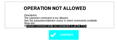
Not connected to PXI: this message means that at least one of the PXIs is not connected, not running properly or powering on, so the user must wait before trying again with the command.
Settings and events database
Where is the database running
How it is installed
How backups are managed (both local and LSST GitHub backup)
Error diagnosis
To fully understand the errors produced in the TMA is very important to have a general knowledge of the TMA, the main hardware components in the TMA are explain in the hardware section.
Most common errors related with hardware are:
EtherCAT line failure, here it can be just some minor issue which can be easily recovered by this procedure or a greater issue, that can not be recovered with the mentioned procedure and this other procedure is required
Bosch controller failure, procedure
Encoder not being able to perform a reference, not homing, this has usually been due to dirt in the encoder tapes. Move somewhere else and try again, if not working, clean the tapes and try again.
There are other faults that can occur that are not actually due to hardware problems, and that can be recovered easily, just knowledge an understanding about the issue is required. Some of these could be:
Pressing a limit switch
Moving too fast causing the system to fail due to over-speed
Temperature alarms, if the system is too far above the setpoint
Temperature warnings, if the system is too far below the setpoint
Pressing an ETPB (emergency trip push button), which causes the system to stop
Having safety interlocks that prevent the movement or activation of a subsystem. For example: trying to power on elevation axis with the locking pins at the inserted position.
There is a windows form available for error/fault reporting from the TMA, when using it is very important to have details of what the sequence was:
All the commands sent before the fault
Command that caused the fault
Command origin (CSC, EUI, HHD)
Time of the fault (UTC preferred)
Is not enough just randomly pasting logs into the form, make an effort understanding the fault message before filling in the fault reporting form
Log files
Location
There are log files in each device running LabVIEW code these files can be found in the following paths for each device:
MCC (Main Control Computer): this is the device running the EUI and C++ Operation Manager. Here the logs can be found at:
Operation Manager log: log file
/var/log/mtmount_operation_manager/log.logEUI logs:
/mnt/telemetry/AlarmHistory: here the received alarms by the EUI are storedErrorHistory: here the software errors from the EUI are storedMemoryLogging: here the memory usage of the EUI is storedTelemetryLogging: here the high frequency telemetry received from the PXIs is storedWindowLogging: here the high frequency telemetry stored during move commands from the EUI are stored
PXIs (AUX, TMA and AXES): all three PXIs follow the same structure for the logging. Here there are two type of logs:
Application startup log, this is stored using linux messages the log file is
/var/log/messagesfor accessing the startup information an alias is available in each PXIlabviewmessagesalias labviewmessages="cat /var/log/messages | grep LabVIEW_Custom"Custom log, these are files generated by the LabVIEW application and are stored in
/home/lvuser/log/
Other Maintenance procedures
Change the Azimuth and Elevation home position offset
There is a setting that allows changing the virtual zero position the telescope uses, for this purpose the following steps must be followed:
Steps for Azimuth:
Power Off both axis (AZ and EL)
Make sure you are logged in a user with
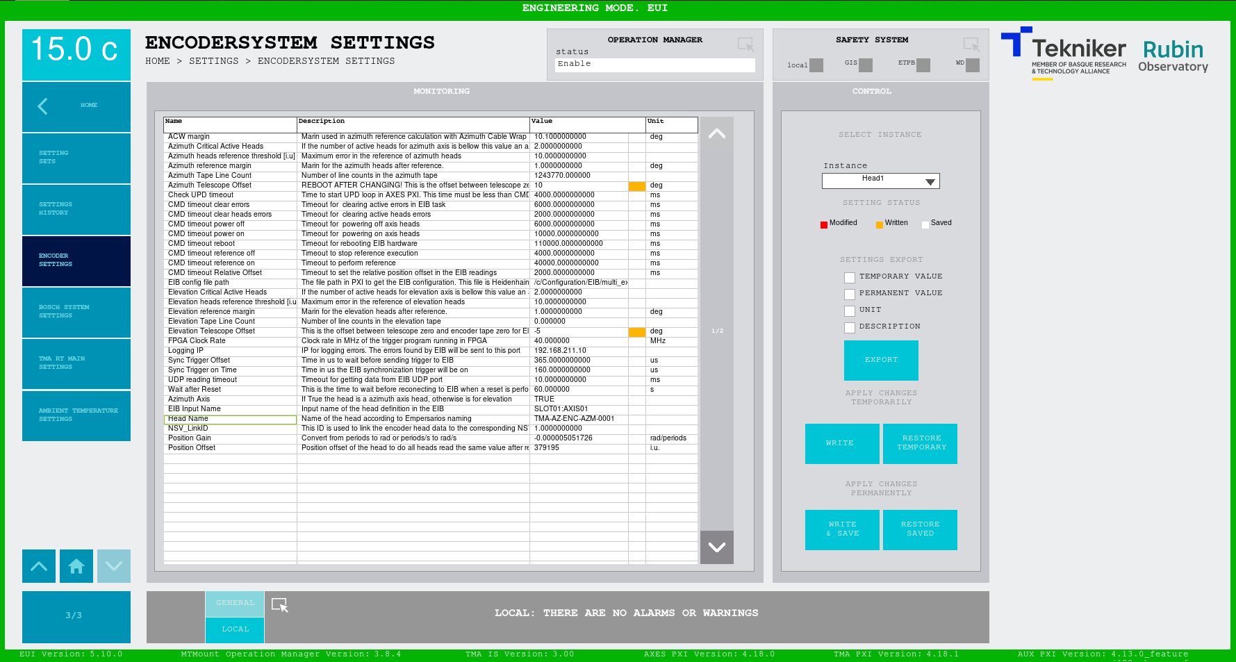
MaintenanceprivilegesGo to the settings window for the Encoder:
ENCODERSYSTEM SETTINGSModify the value of the setting Azimuth Telescope Offset, note that the value is subtracted from the calculated position, so for virtually moving the zero to positive, negative values must be used.
Reboot the TMA-PXI: this must be done only for azimuth but is crucial. If TMA PXI is not rebooted the ACW won’t be centered with azimuth and the system can be damaged.
Power on the azimuth axis and make a reference, the new 0 value should be at the desired position.
Steps for Elevation:
Power Off both axis (AZ and EL)
Make sure you are logged in a user with
MaintenanceprivilegesGo to the settings window for the Encoder:
ENCODERSYSTEM SETTINGSModify the value of the setting Elevation Telescope Offset, note that the value is subtracted from the calculated position, so for virtually moving the zero to positive, negative values must be used.
Power on the elevation axis and make a reference, the new 0 value should be at the desired position.
Example with values:
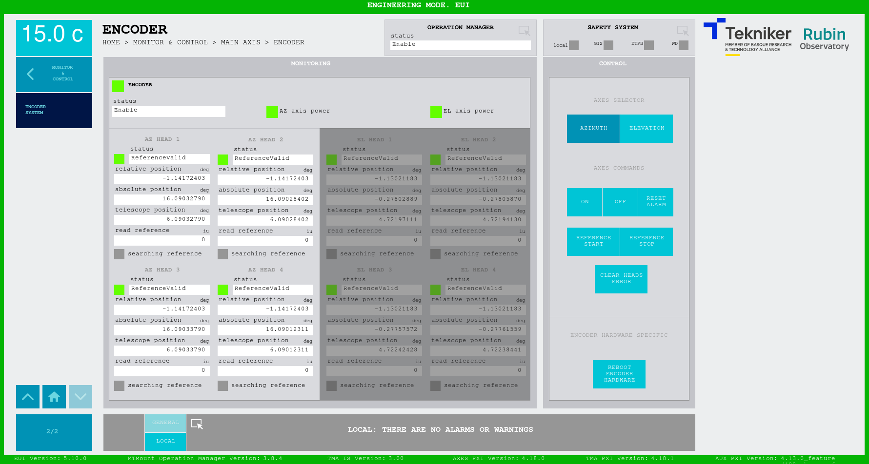
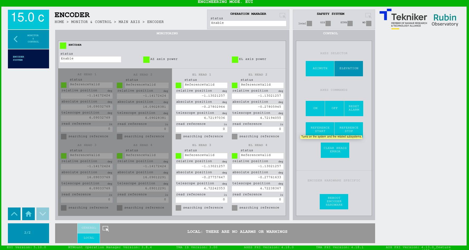
Here there is an example with screenshots for the following changes
Azimuth Telescope Offset: 10 deg
Elevation Telescope Offset: -5 deg
