Locking Pins Screen
Locking Pins Screen – Main View
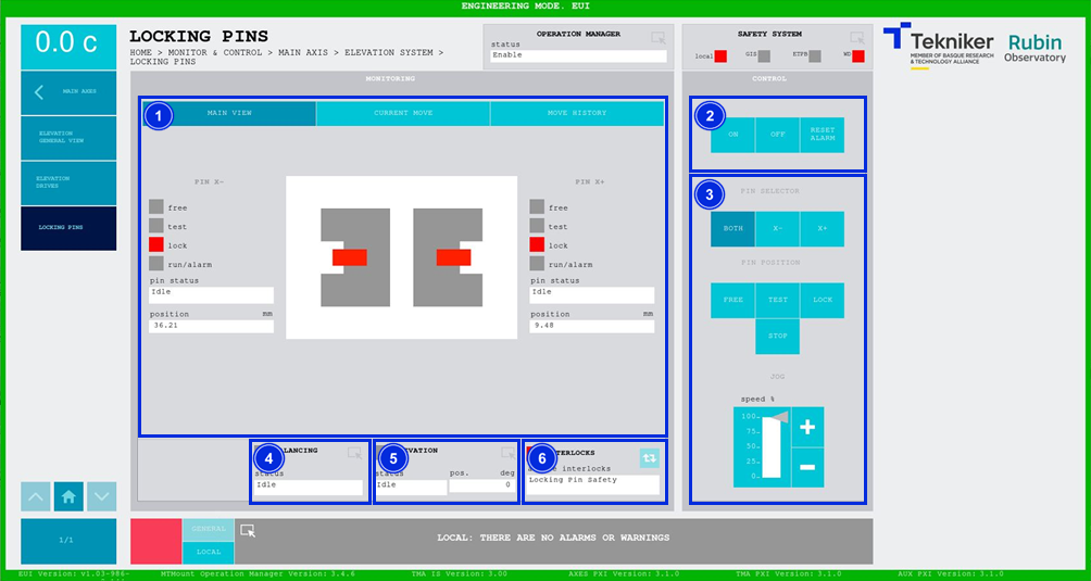
This screen displays the elevation axis locking pins and enables their control.

Figure 2‑20. Locking pins screen - main view.
ITEM |
DESCRIPTION |
||
|---|---|---|---|
1 |
Displays the status of the locking pins:
Displays the status and position (in mm) of the locking pins. In addition, the box next to “run/alarm” lights up in the color corresponding to the status of the pin. |
||
2 |
Softkey “ON”: Only turns on the pin if it is in “Idle” and no interlock is active. Softkey “OFF”: Turns off the pin. Softkey “RESET ALARM”: Resets the system from its current alarm state or resets the interlock if one exists. |
||
3 |
Softkey “BOTH”: Selects both pins. Softkey “X-”: Selects the pin located in the “X-” bracket. Softkey “X+”: Selects the pin located in the “X+” bracket. Softkey “FREE”: Moves the previously selected pin to the released position. Softkey “TEST”: Moves the previously selected pin to the test position. Softkey “LOCK”: Moves the previously selected pin to the lock position. Softkey “STOP”: Stops the movement of the previously selected pin. Softkeys “+” or “-”: Makes a movement at a constant speed in a positive or negative direction respectively. This sets the percentage of the default speed defined in the settings with the vertical slider. |
||
4 |
Displays the status and allows access to the screen [“Balancing General View”](./024_BalancingGeneralView.md) |
||
5 |
Displays the status and position (in deg) of “Elevation”. Accesses the screen Elevation General View |
||
6 |
The blue softkey navigates between the active interlocks, if there is more than one. When an interlock is active, the top box is displayed in red. If no interlocks are active, the box will be green and the blue softkey cannot be pressed. |
Locking Pins move sequence
The locking pins have 3 positions:
Free: the locking pins are completely retracted, allowing a complete and free movement of the Elevation axis.
Lock: the locking pins are completely inserted, restricting the Elevation axis movement. This restriction is both mechanical and electrical, as the signal from the limit switch is wired to the TMA IS disabling the Elevation axis. The active “Locking Pin Safety” interlock will appear in the “INTERLOCKS” box, accompanied by the red box.
Test: the locking pins are at an intermediate position, at this position the elevation axis has a few degrees of free motion before hitting the locking pins. This position in meant just for balancing purposes, to limit the motion range allowed for elevation during the process.
As there are just 3 possible positions for the locking pins, for motion there are just 3 buttons named accordingly, to move the pins to the corresponding positions.
The sequence to move the locking pins from one position to another is:
Turn ON power to the locking pins. The “pin status” will change from “Idle” to “Enable”. If an interlock is present, press RESET ALARM, then ON.
Choose BOTH to move both locking pins, or +X, -X, if you are only moving the locking pin in the +X or -X bracket, respectively.
Push FREE, TEST or LOCK buttons to command to the new position.
The locking pins will take around a minute to get into the new commanded position. The display section will show the new position highlighted with the color code described above.
Turn the locking pins OFF. The “pin status” will return to “Idle”.
The position in mm for each pin is stored as a setting and can be adjusted by a maintenance user in the EUI settings. Additionally, maintenance users may see the jog buttons for adjusting these positions; other users will just see the FREE, TEST and LOCK buttons for moving the pins.
Locking Pins Screen – Current Move
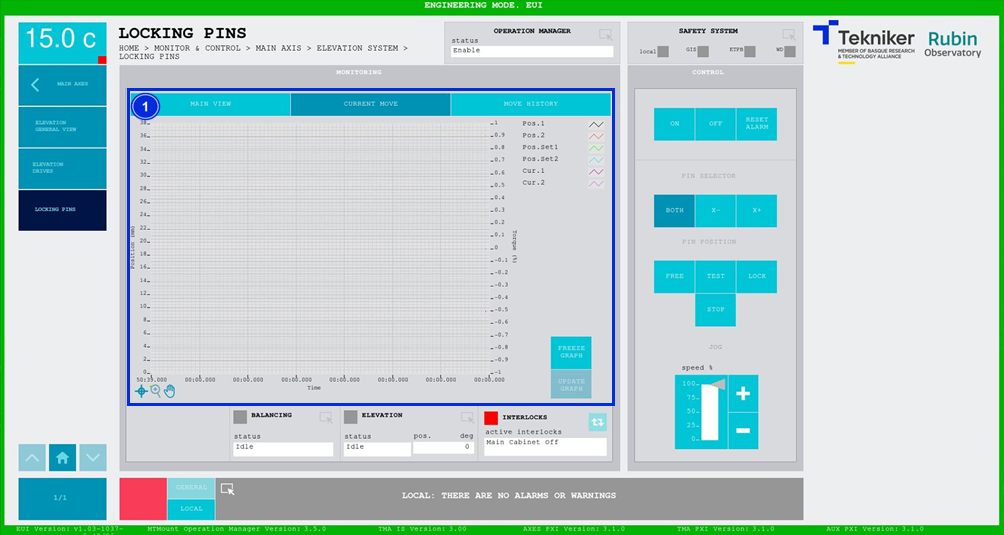
This screen shows a graph of the movement of the locking pins in real time.

Figure 2‑21. Locking pins screen - current move.
ITEM |
DESCRIPTION |
|---|---|
1 |
Displays a graph of the movement of the locking pins in real time. Softkey “FREEZE GRAPH”: Freezes the graph. Softkey “UPDATE GRAPH”: Allows the graph to be updated after being frozen. |
Locking Pins Screen – Move History
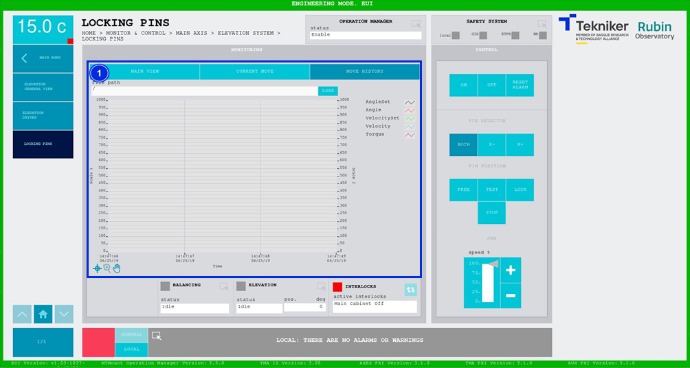
This screen displays and loads the last five movements of the locking pins, with number 1 being the last.

Figure 2‑22. Locking pins screen - move history.
ITEM |
DESCRIPTION |
|---|---|
1 |
Softkey “LOAD”: Loads the last five movements. Once the desired movement has been selected, it allows it to be displayed on the graph. |