Bosch task
This document describes the task used to communicate with the bosch system, from now on called Bosch task. This task contains some public methods that must be used to send the required actions to the wanted bosch axis.
Task public methods
Here the methods for the Bosch task are explained.
InitSubsystem
Used to initialize the subsystem. Do it before starting the statechart, as part of the subsystem init actions. This method will be the only one that will wait until the task answers to keep going. The task could answer an error or nothing is everything goes fine.
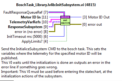
Inputs:
MotorID: the identifier of the motor. From this moment on, this ID will be the reference the data related to the subsystem/motor.
FaultResponseQueueRef: the queue used to publish the error info when a fault is triggered from the task. Saved in the task related to the motor ID.
TelemetryVarRefs: variables used to publish the telemetry of the system. Saved in the task related to the motor ID. If the variable is left empty nothing will be published for that topic.
TrackActive? var ref. Boolean type var.
Position var ref. DBL array type var.
Velocity var ref. DBL array type var.
Status var ref. String type var.
Status code var ref. I32 type var.
Torque var ref. DBL array type var.
Acceleration var ref. DBL array type var.
Positive limit: Limit.ctl
LimitVar2Publish Boolean type var.
Negate?
Bit
Negative limit: Limit.ctl
LimitVar2Publish Boolean type var.
Negate?
bit
ResponseSubsystem: an input of the SubsystemGeneral.lvclass, is used to have the dynamic dispatch to the actual subsystem. Saved in the task related to the motor ID.
Error In: transmits the error.
InitTimeout ms: this is the timeout of the CMD, if this timeout is exceeded the subsystem did not start well and an error is triggered.
Apply limits?: this is to tell the system that has to check for the limits of the subsystem or not.
CloseTask
Method to close the app.
ExitSubsystem
Method to exit a subsystem, this means closing the related refs.
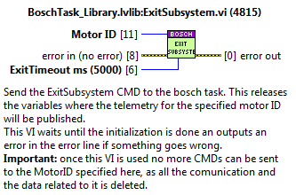
Inputs:
MotorID: the identifier of the motor. The reference to the data related to the subsystem/motor.
ExitTimeout ms: this is the timeout of the CMD, if this timeout is exceeded the subsystem did not stop well and an error is triggered.
Get Axis Info
Returns the position and speed. The values are taken from FGV_AxisInfo.
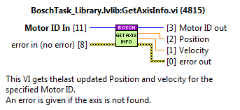
Inputs:
MotorID: the identifier of the motor. The reference to the data related to the subsystem/motor.
Move
Used for a Move CMD.
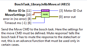
Inputs:
MotorID: the identifier of the motor.
Timeout ms: the timeout value for the CMD. If not wired the default value is -1, this means that timeout is not applied.
Settings: MotionMoveAbsolute.ctl from MLPI
Position
Velocity
Acceleration
Deceleration
Jerk
MuteResponse?: used to mute the answer to the statechart.
MoveVelocity
Used for a MoveVelocity CMD.
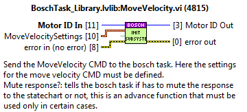
Inputs:
MotorID: the identifier of the motor.
Settings: MotionMoveVelocity.ctl from MLPI
Velocity
Acceleration
Deceleration
Jerk
MuteResponse?: used to mute the answer to the statechart.
Power
Used for a Power CMD.
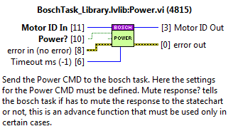
Inputs:
MotorID: the identifier of the motor.
Timeout ms: the timeout value for the CMD. If not wired the default value is -1, this means that timeout is not applied.
Settings:
Power?: Tells the bosch task if has to turn on the axis or turn it off.
MuteResponse?: used to mute the answer to the statechart.
GetAxisStatus
Obtain the status of a specified Axis. Alberto thinks it’s interesting to know the status if the axis is in fault or in parking.
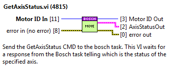
Inputs
MotorID: the identifier of the motor.
Reset
Used for the Reset CMD.
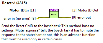
Inputs:
MotorID: the identifier of the motor.
MuteResponse?: used to mute the answer to the statechart.
Stop
Used for the Stop CMD.
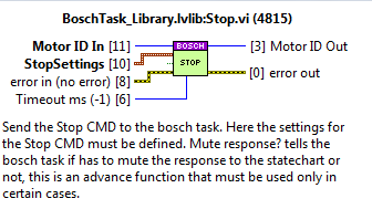
Inputs:
MotorID: the identifier of the motor.
Timeout ms: the timeout value for the CMD. If not wired the default value is -1, this means that timeout is not applied.
Parameters: StopSettings_TypeDef.ctl
Deceleration
Jerk
MuteResponse?: used to mute the answer to the statechart.
Track
Used for the Track CMD. The Bosch task does no longer have the tracking inside, the track CMD available just sends the move continuous when received to the specified axis.
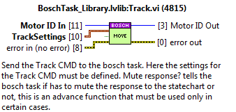
Inputs:
MotorID: the identifier of the motor.
Parameters:
Parameters: MoveContinuousAbsolute
Position
endVelocity
Velocity
Acceleration
Deceleration
Jerk
WaitTaskReady
Wait for the bosch task to be ready. This is used to avoid starting the subsystems that use the bosch task before the Bosch task is ready.
PrePowerSupplyWaitActions
This VI executes the actions required before waiting for the bosch power supply to be ready. Actions:
Set the variables GBL_BoschTaskReady and GBL_StopWaitTaskReady to FALSE
Init and Exit Actions
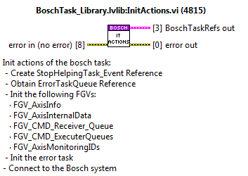
Init actions
Init actions of the bosch task:
Create StopHelpingTask_Event Reference
Obtain ErrorTaskQueue Reference
Init the following FGVs:
FGV_AxisInfo
FGV_AxisInternalData
FGV_CMD_Receiver_Queue
FGV_CMD_ExecuterQueues
FGV_AxisMonitoringIDsInit needed queues and DVRs
Init the error task
Send Connect to the PLC
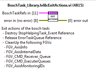
Exit actions
Exit actions of the bosch task:
Destroy StopHelpingTask_Event Reference
Release ErrorTaskQueue Reference
CleanUp the following FGVs:
FGV_AxisInfo
FGV_AxisInternalData
FGV_CMD_Receiver_Queue
FGV_CMD_ExecuterQueues
FGV_AxisMonitoringIDs
Task loops
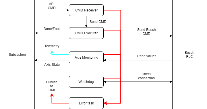
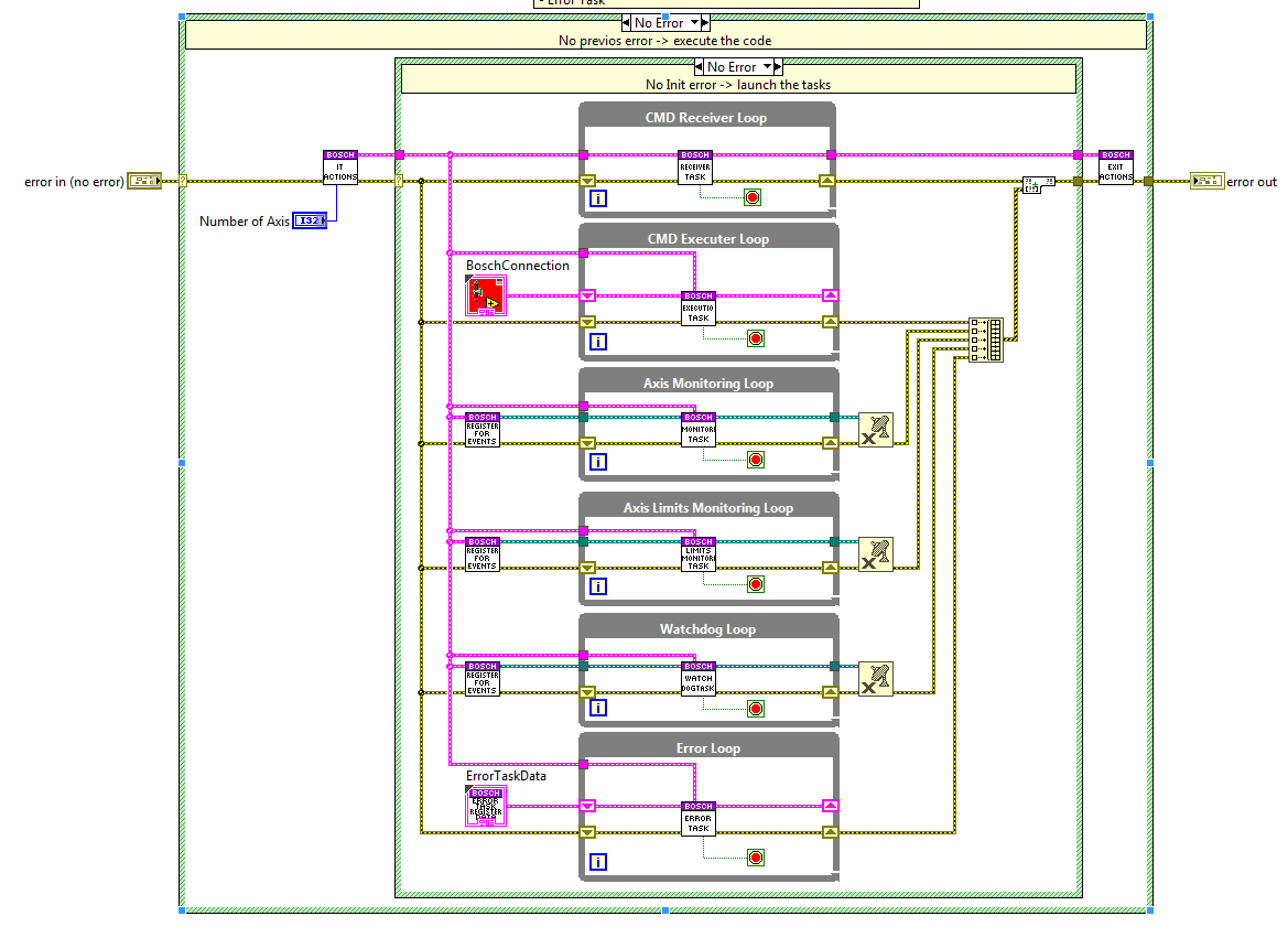
The bosch task has 5 tasks inside that manage different parts needed to operate the bosch system, each of them is explained in the upcoming sections.
CMD Receiver loop
This loop receives the CMDs from the API and executes the required actions for each CMD.
Task communication
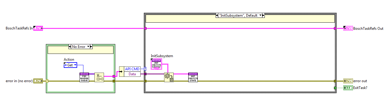
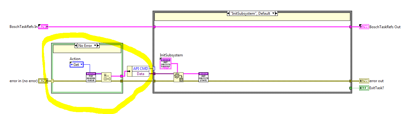
The communication between the methods and the task is very simple and is done using a queue. This queue is initialized at the init actions of the bosch task and released at the exit actions. The reference of the queue is saved to a FGV, this FGV is called: “FGV_CMD_Receiver_Queue.vi” see figure below.
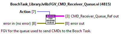
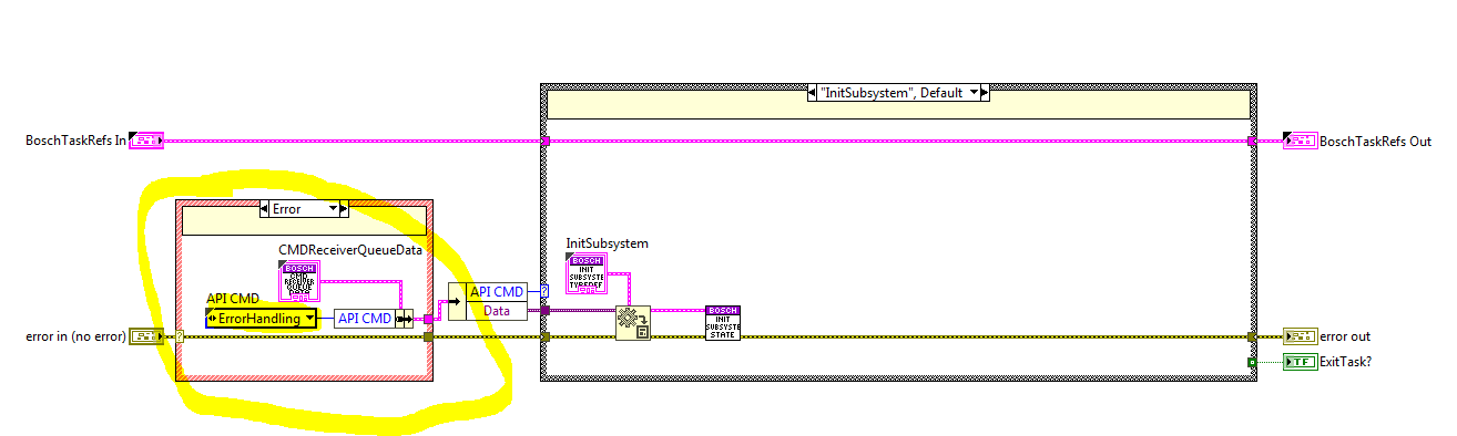
Each of the methods uses this queue to enqueue the next CMD and the CMD receiver loop dequeues the CMDs from the queue at the beginning of each iteration, see figure below. If an error occurred at the previous iteration the ErrorHandling state is executed and the last CMD will be dequeued in the next iteration, see figure below.
Methods
The methods of this loop are explained before as public methods of the bosch task.
Task commands
Here the code for the different task commands is explained.
Init Subsystem
The code here is used when a new subsystem is added, the reference for this subsystem will be the MotorID. To initialize this new system the following actions are executed:
Open the telemetry variable connections.
Save all the subsystem data inside an indexed FGV, “FGV_AxisInternalData”, this FGV is private to ensure that data is only accessed from inside the library.
Save the initialized MLPI axis in another FGV, “FGV_AxisMonitoringIDs”, this FGV is used at the monitoring loop, all the axis here are checked and the data related to it is published at the telemetry vars saved at the FGV_AxisInternalData.
Init the queue for this MotorID, this is done inside another FGV, “FGV_ExecuterQueues”, this FGV saves the queue ref of each initialized motorID. This is done like this to ensure that each system has an independent queue and to enable simultaneous CMDs.
Finally, a response is sent to the calling method, the response is just the error line, this way the calling VI will know if everything was ok while initializing.

Exit Subsystem
The code here is used when an existing subsystem is removed, the reference for this subsystem will be the MotorID. To exit the existing system the following actions are executed:
Open the telemetry variable connections.
Save all the subsystem data inside an indexed FGV, “FGV_AxisInternalData”, this FGV is private to ensure that data is only accessed from inside the library.
Save the initialized MLPI axis in another FGV, “FGV_AxisMonitoringIDs”, this FGV is used at the monitoring loop, all the axis here are checked and the data related to it is published at the telemetry vars saved at the FGV_AxisInternalData.
Init the queue for this MotorID, this is done inside another FGV, “FGV_ExecuterQueues”, this FGV saves the queue ref of each initialized motorID. This is done like this to ensure that each system has an independent queue and to enable simultaneous CMDs.
Finally, a response is sent to the calling method, the response is just the error line, this way the calling VI will know if everything was ok while initializing.

Close Task
Stops the rest of the tasks executed in the bosch task, as well as this one, while closing any open connections.
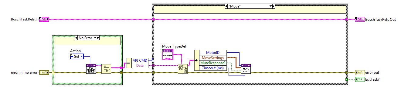
Move
The code is executed when the move method is used, here the MoveCMD private method from the Executer task is called.
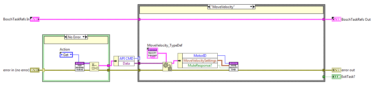
Move Velocity
The code is executed when the moveVelocity method is used, here the MoveVelocityCMD private method from the Executer task is called.
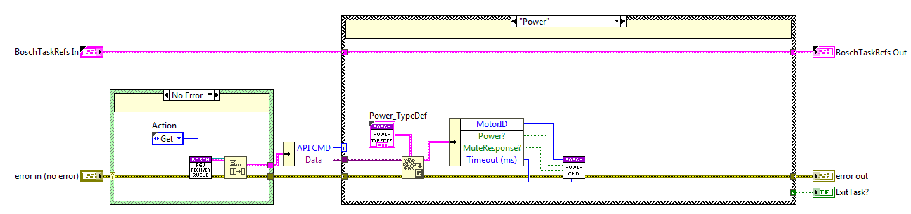
Power
The code is executed when the power method is used, here the PowerCMD private method from the Executer task is called.
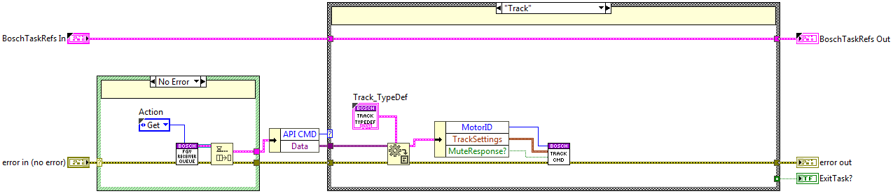
Track
The code is executed when the track method is used, here the TrackCMD private method from the Executer task is called.
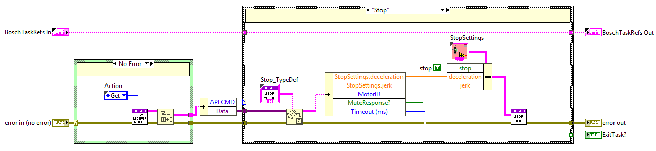
Stop
The code is executed when the stop method is used, here the StopCMD private method from the Executer task is called.
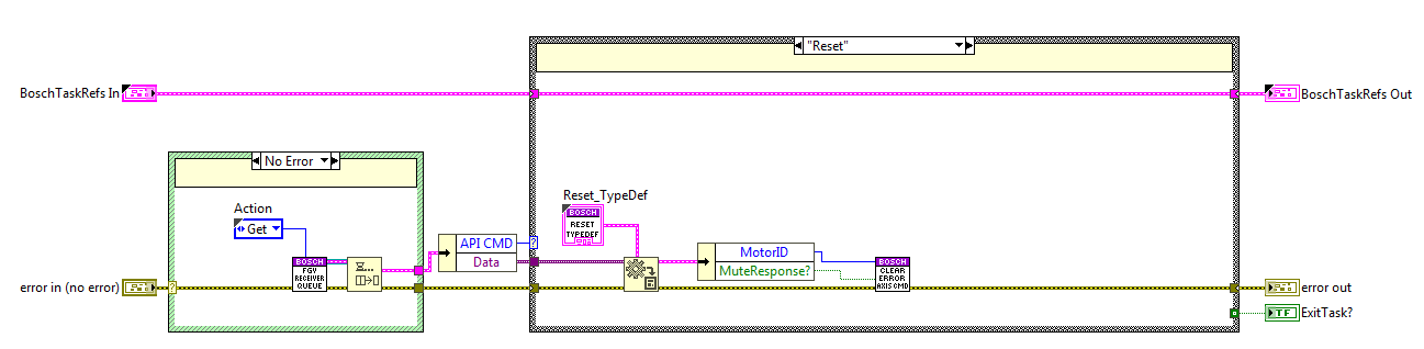
Reset
The code is executed when the reset method is used, here the ResetCMD private method from the Executer task is called.
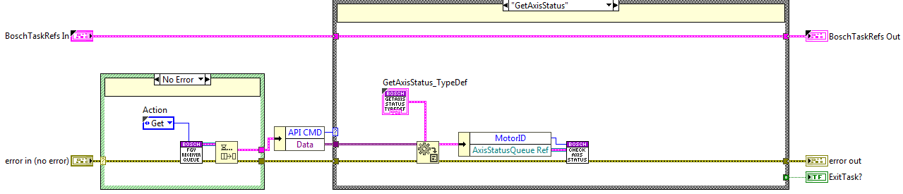
Get Axis Status
The code is executed when the getAxisStatus method is used, here the CheckAxisStatus private method from the Executer task is called.
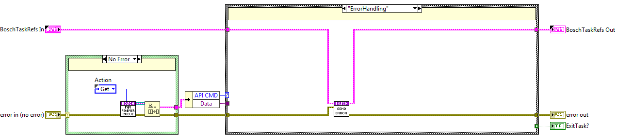
Error Handling
The code is executed when an error occurs at the error line, here the method from the error task send error is used.
CMD Executer loop
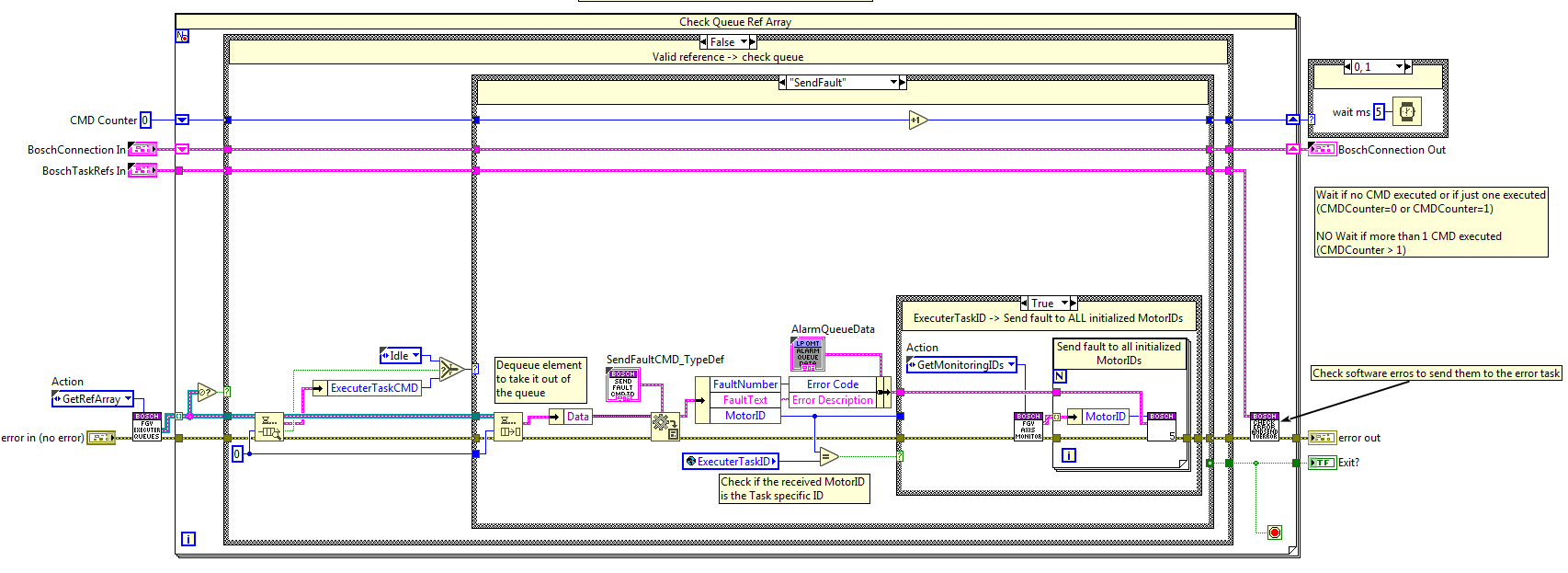
This loop receives actions from the CMD receiver and communicates with the Bosch PLC. This loop includes the CMD monitoring, this means that when one CMD takes time to execute a new state is enqueued after sending it to the Bosch system to check the CMDs progress.
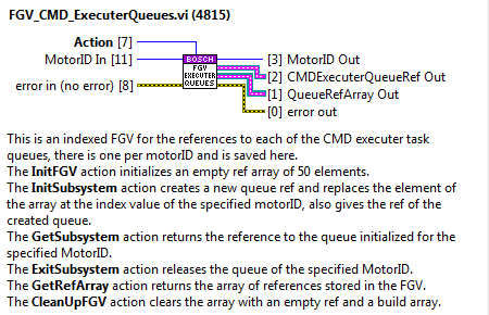
Task communication
The communication between the methods and the task is not as simple as the one for the CMDReceiver task. Here CMDs must be executed in parallel for more than one MotorID, that’s why there must be more than one queue. To solve this problem and to avoid using lvclasses, that cause problems when deploying to a RT target, the adopted solution is an FGV with a queue array, “FGV_CMD_ExecuterQueues” see Figure 30, each of the queue references of the array is linked to one MotorID. This queue is initialized at the InitSubsystem state of the CMD Receiver task and released at the ExitSubsystem state.
Each of the methods uses the queue related to the specified MotorID to enqueue the next CMD and the CMD executer loop gets all the queues of each iteration. This array is then indexed, and all the queue references are checked for available CMDs.
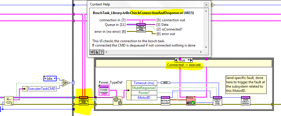
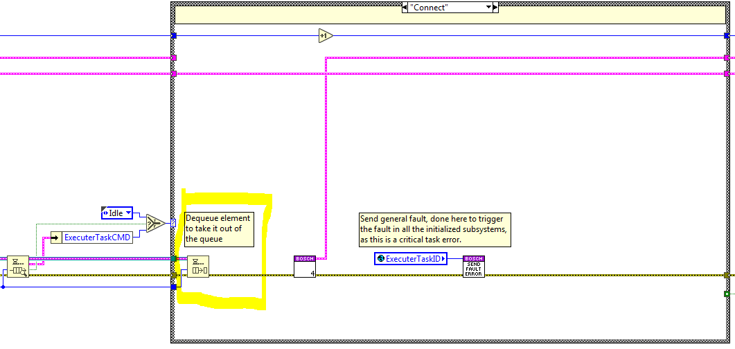
At first the elements in the queue are not dequeued, first the element is previewed. After, at the selected state the required actions are done. Some of the states need to check the connection status before executing the state, see figure below, others do not need to do that and dequeue the queue at the beginning of the state, see figure below.
Methods
Here the methods of this task are explained. All the methods listed below are private methods that only can be accessed from inside the library.
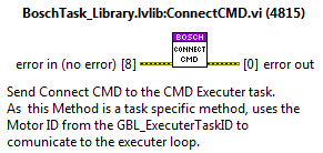
ConnectCMD
Connect task to the Bosch system.
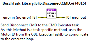
DisconnectCMD
Disconnect task from the Bosch system.
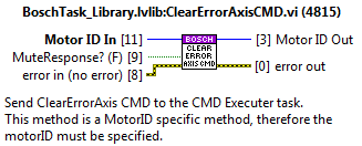
ClearErrorAxisCMD
Reset error from the specified MotorID.
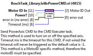
PowerCMD
Send power on/off to the specified MotorID.
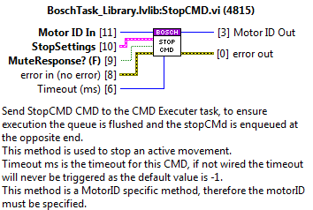
StopCMD
send stop to the specified MotorID.
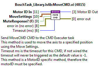
MoveCMD
Send move absolute to the specified MotorID.
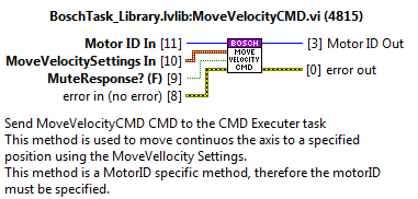
MoveVelocityCMD
Send move velocity to the specified MotorID.
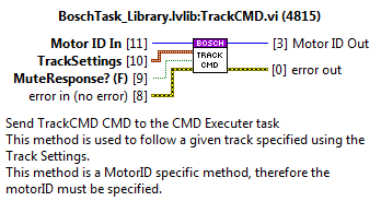
Track
Send move continuous to the specified MotorID.
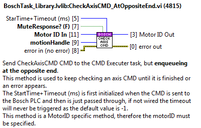
CheckAxisCMD_AtOppositeEnd
Checks the specified motionHandle to trigger the statechart when finished or when an error occurs.
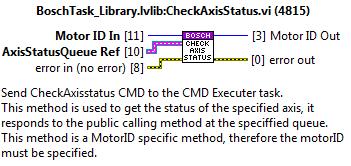
CheckAxisStatus
Checks the status of the specified MotorID and answers at the specified AxisStatusQueue.
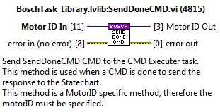
SendDoneCMD
Sends the done trigger to the statechart linked to the specified motorID.
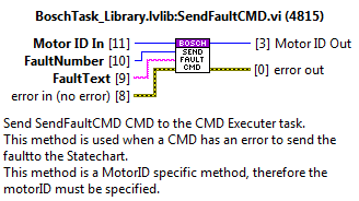
SendFaultCMD
Sends the fault trigger to the statechart linked to the specified motorID. Sends the info of the fault to the statechart using the queue ref saved at the FGV_AxisInternalData.
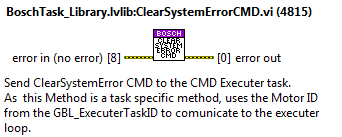
ClearSystemErrorCMD
This is a task specific method and is used to clear the general errors of the bosch system.
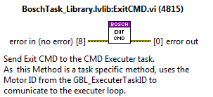
ExitCMD
This is a task specific method and is used to close the task.
Task states
Here the code for the different task states is explained.
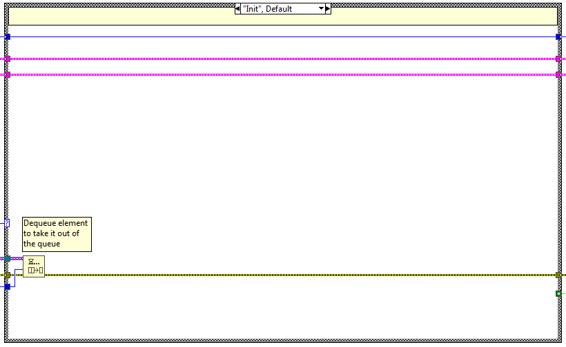
Init
Perform the init actions of the task. [Nothing so far.]{.mark}
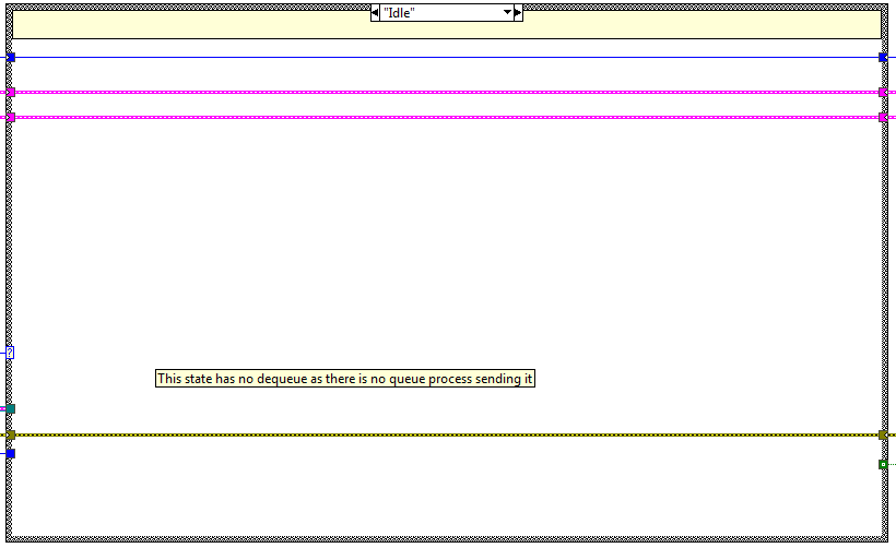
Idle
Empty state just to do nothing and wait until another CMD is available.
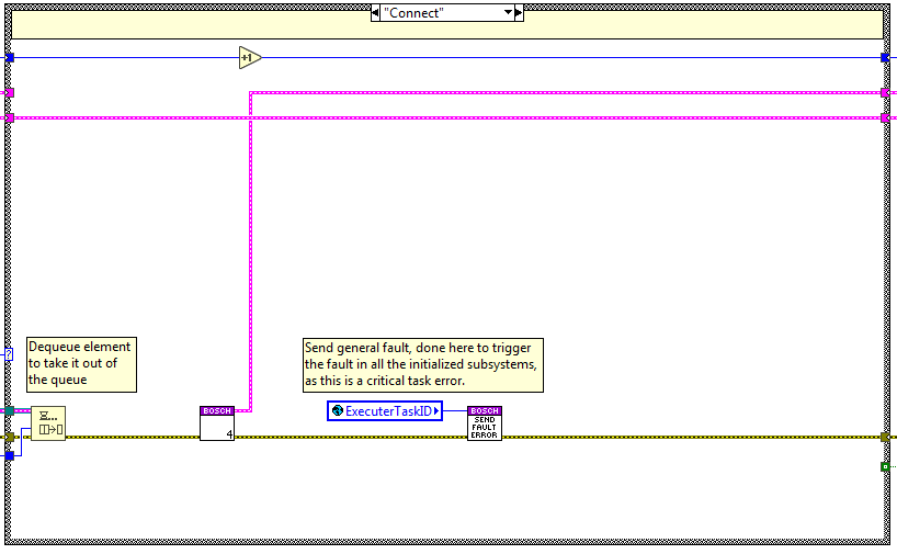
Connect
The code is executed when the connect method is used, here the Connection to the Bosch system is done, the connection handle is saved in a FGV (“FGV_BoschConnection”) to access it from the axis monitoring loop.
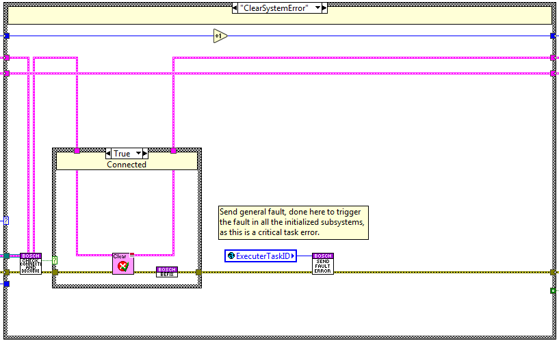
ClearSystemError
The code is executed when the clearSystemError method is used, here the function clear error from the Bosch system is done.
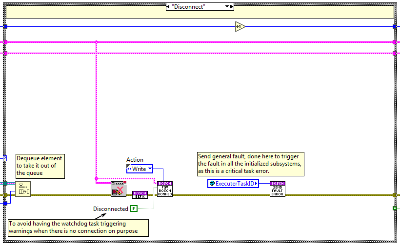
Disconnect
The code is executed when the disconnect method is used, here the disconnection from the Bosch system is done, the closed connection handle is saved in a FGV (“FGV_BoschConnection”) to access it from the axis monitoring loop.
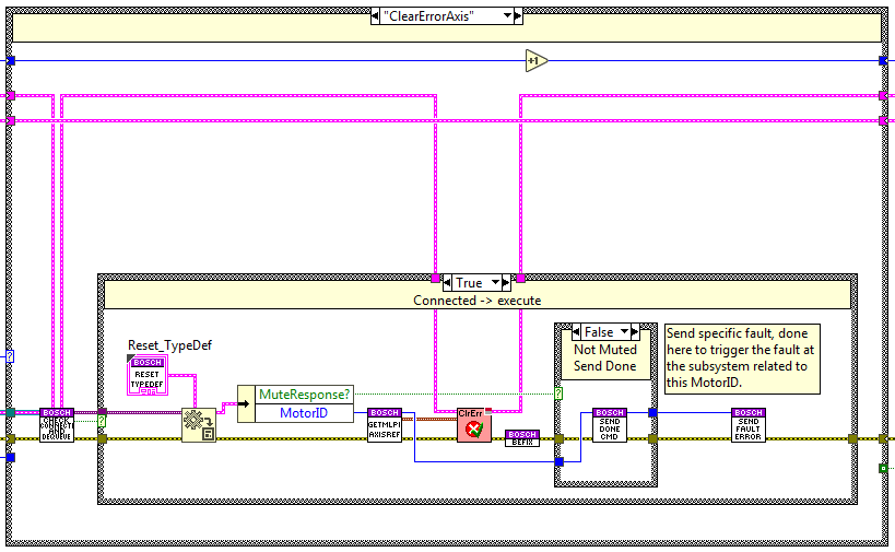
ClearError Axis
The code is executed when the ClearErrorAxis method is used, here the errors from the axis linked to the specified MotorID are cleared. When done a done response is sent to the statechart related to the MotorID, unless the response is muted.
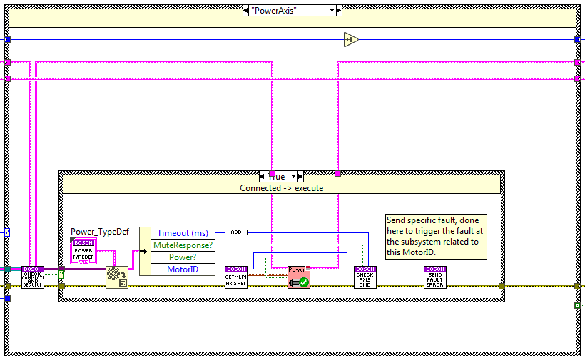
Power Axis
The code is executed when the power method is used, here the axis linked to the specified MotorID is powered on or off depending on the specified boolean value. To know when done a new state is enqueued at the opposite end of the queue CheckAxis state, this state checks if the CMD is done, if it has an error and if it was timed out.
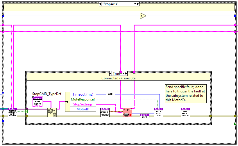
Stop Axis
The code is executed when the stop method is used, here the axis linked to the specified MotorID is stopped using the deceleration and jerk specified as settings. To know when done a new state is enqueued at the opposite end of the queue Check Axis state, this state checks if the CMD is done, if it has an error and if it was timed out.
Move Axis
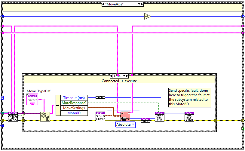
The code is executed when the move method is used, here the axis linked to the specified MotorID is moved to the specified absolute position using the acceleration, deceleration and jerk specified as settings. To know when done a new state is enqueued at the opposite end of the queue Check Axis state, this state checks if the CMD is done, if it has an error and if it was timed out.
MoveVelocity Axis
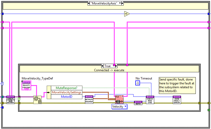
The code is executed when the moveVelocity method is used, here the axis linked to the specified MotorID is moved at the specified velocity using the acceleration, deceleration and jerk specified as settings. To know if an error occurs during the move a new state is enqueued at the opposite end of the queue Check Axis state, this state checks if the CMD is done, if it has an error and if it was timed out, but for this specific CMD the only important check is the error check, as a move velocity can´t have a done or a timeout.
Track Axis
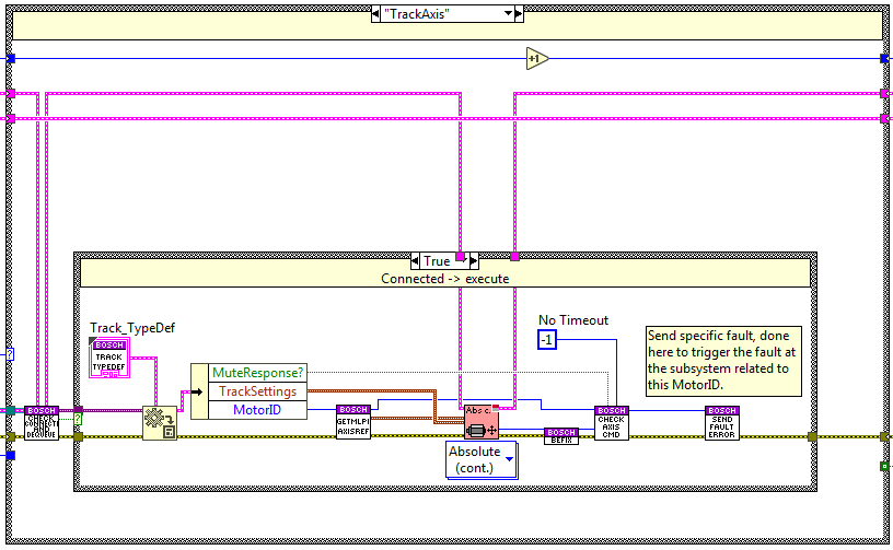
The code is executed when the track method is used, here the axis linked to the specified MotorID is moved to the specified position using the endSpeed, acceleration, deceleration and jerk specified as settings. To know if an error occurs during the move a new state is enqueued at the opposite end of the queue Check Axis state, this state checks if the CMD is done, if it has an error and if it was timed out, but for this specific CMD the only important check is the error check, as a track can´t have a done or a timeout.
CheckAxisCMD
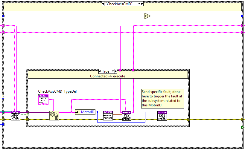
This state checks the CMD status, this means that it checks if the CMD is done, if it has an error and if it was timed out.
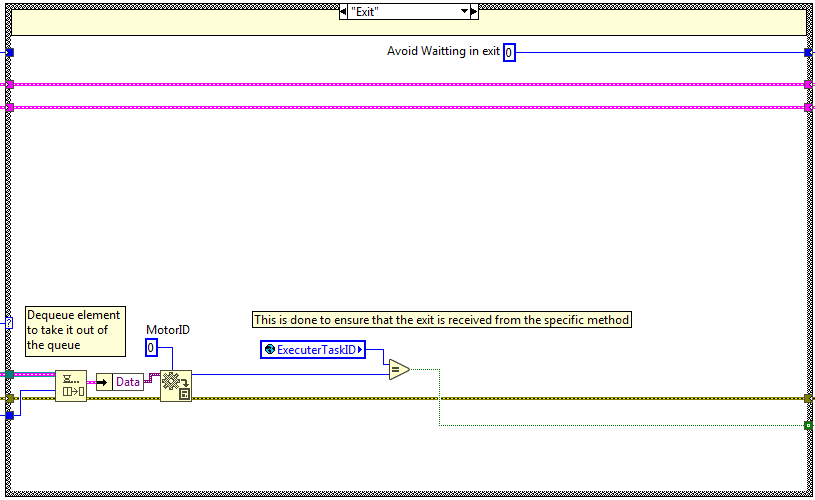
Exit
This case is used to exit the task, here is checked that the calling method is the task exclusive MotorID that is the 0.
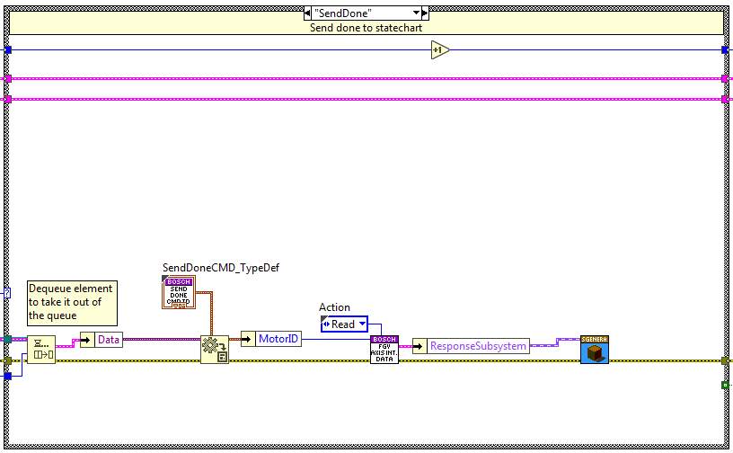
Send Done
The code is executed when the send done method is used, here a done trigger is sent to the statechart linked to the specified MotorID.
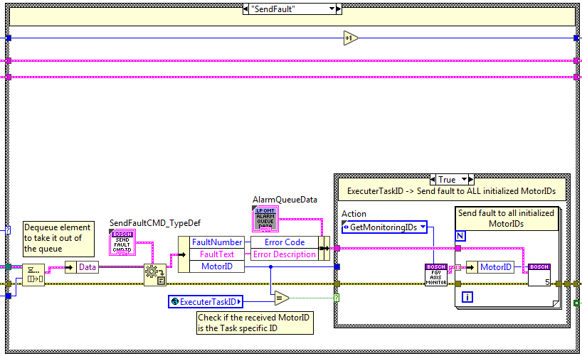
Send Fault
The code is executed when the send fault method is used, here a fault trigger is sent to the statechart and the faultResponseQueue is updated with the fault information linked to the specified MotorID.
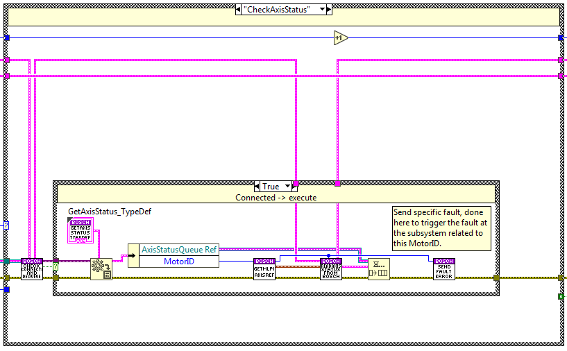
Check Axis Status
The code is executed when the check axis status method is used, here the status of the axis linked to the specified
MotorID is checked and updated in the response queue called AxisStatusQueue re, this queue is dequeued at the calling
public method GetAxisStatus.
Axis Monitoring task
This task is divided in two loops, one for the axis values (position, velocity, acceleration, torque and status) and the other loop is used to read the limits status (positive and negative limit switch). This is done like this, due to the delay when reading the limits.
Axis values monitoring loop
This loop publishes the telemetry given by the TCP communication with the PLC code in the Bosch Controller. The received
values are parsed with the structure defined in the BoschTcpTelemetry_TypeDef.ctl. From all this data the wanted
defined one is only published, to do so at the initSubsystem the wanted variables must be specified, if no variable is
specified that value is not published.
The telemetry vars published here are opened at the InitSubsystem stage of the CMD Receiver and closed at the ExitSubsystem stage.
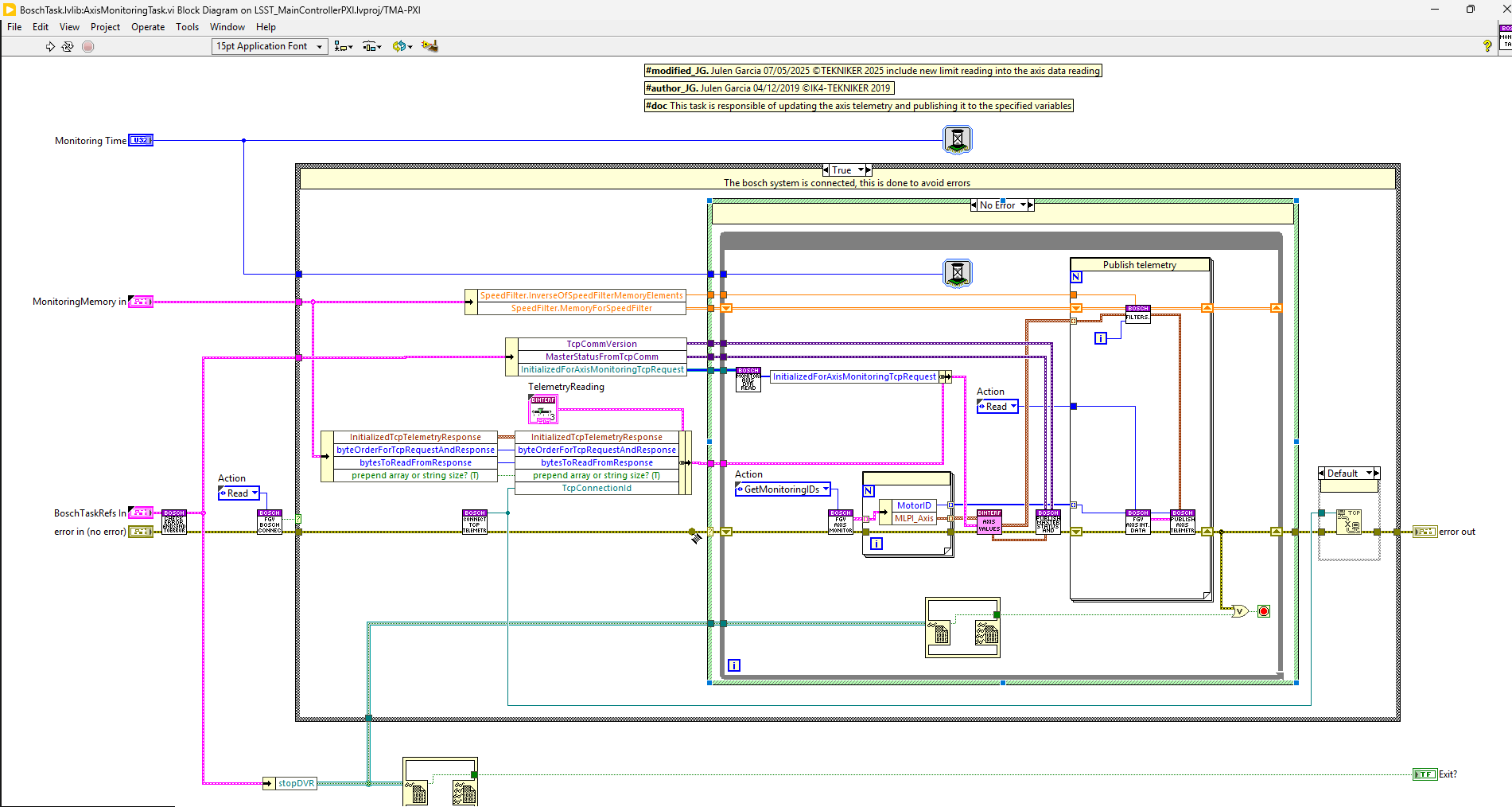
Task communication
This task has no communication with the rest of the tasks, but it contains the TCP communication with the Bosch Controller to obtain the telemetry values, which are published periodically.
The only communication is the stop flag read from a DVR for stopping the loop.
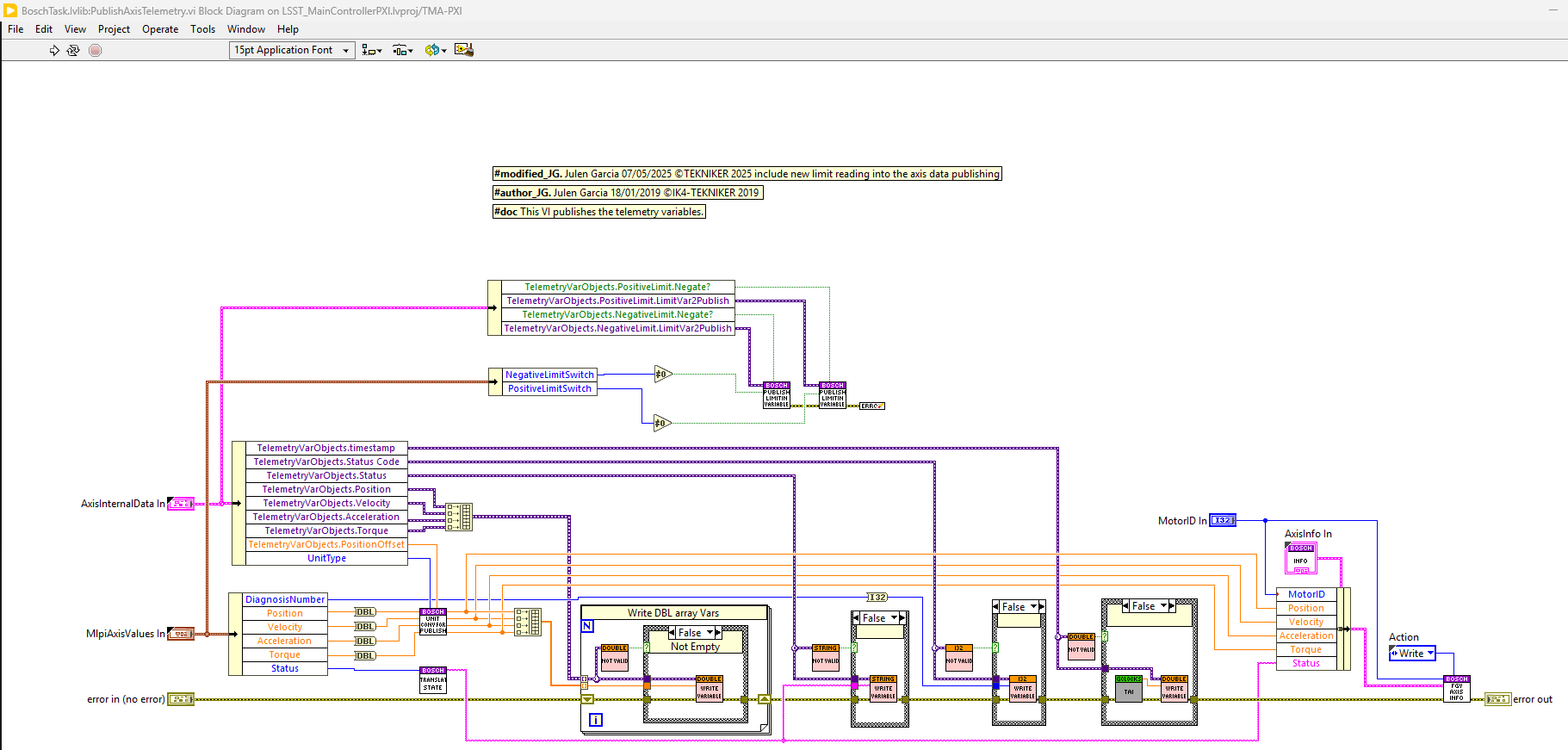
Publishing vars
Here the variables that can be published for each motor id:
Name |
Variable Type |
|---|---|
Position |
DBL |
Velocity |
DBL |
Acceleration |
DBL |
Torque |
DBL |
Timestamp |
DBL |
Status |
String |
Status Code |
I32 |
Positive Limit |
Bool |
Negative Limit |
Bool |
Watchdog
This task is responsible of keeping the connection between the PXI and the Bosch system.
If the connection is Okay this task does nothing.
If the connection is NotOkay this task Sends a Connect CMD to the executer task and a warning to the HMI. If this happens more than 5 times a fault is sent to all the initialized subsystems.
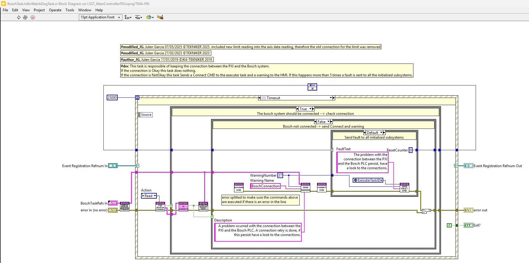
Task communication
This task has no communication, this task is checking if the connection is working between the bosch system and the PXI, if okay nothing is done, but if not working a warning is sent.
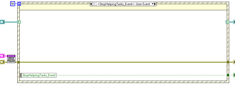
The only communication is the stop event launched from the CMD receiver Close task state.
Error task
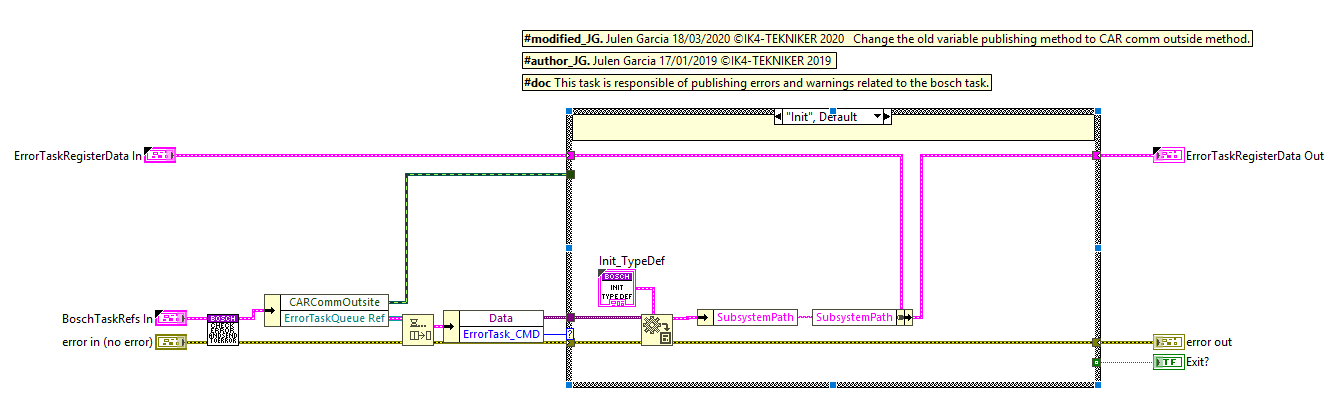
This task publishes the software errors and warnings related to the Bosch task.
Task communication
This task has a single queue and the methods use it to publish the available states, these methods are private methods. The queue reference is created at the InitActions and released at the ExitActions of the bosch task. The reference is saved to a cluster, “BoschTaskRefs”, as it has no need to be used out of the library main VI.
Methods
The methods available for this task are described in the upcoming sections.
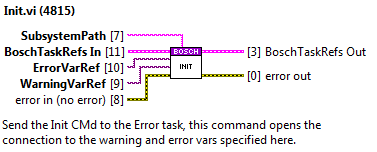
Init
This method enqueues the init state of the error task.
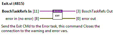
Exit
This method enqueues the exit state of the error task.
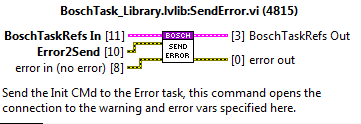
Send Error
This method enqueues the send error state of the error task and sends the error cluster wired to the Error2Send as CMD data.
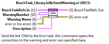
Send Warning
This method enqueues the send warning state of the error task and sends the Waring number, warning name and description as CMD data.
External CMD Receiver Loop
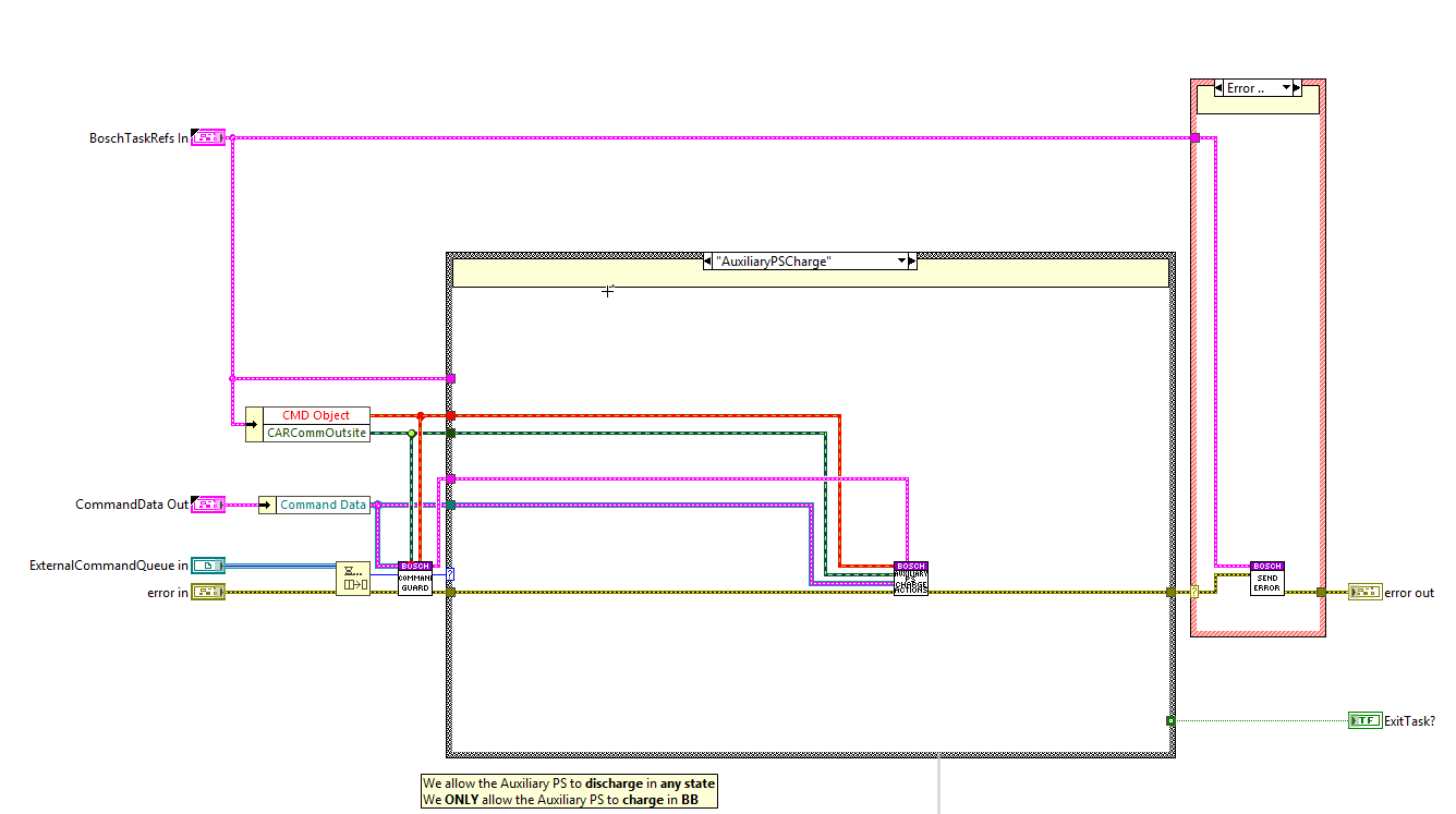
This loop manages the external commands for the task, the ones that can come from the EUI/CSC/HHD. For doing so, this task receives, accepts/rejects, executes and fails/completes/supersedes the commands.
Task communication
This task receives the external commands as a normal subsystem would, using the CAR implementation, which enqueues a trigger depending on the requested command. The queue is dequeued in this loop and processed.
Available Commands
Command Number |
Command Name |
|---|---|
3101 |
|
3102 |
|
3103 |
|
3104 |
|
3105 |
|
3106 |
|
3107 |
|
3108 |
|
3109 |
|
3110 |
|
3111 |
ChangeToBB
Interlocks: None
Actions:
Accept the command
Set the Bosch Controller mode to
BBWait for the Bosch Controller to be in
BBmodeSend completed or failed depending on previous step outcome (the failed can be either a software error or a wait timeout)
ChangeToP0
Interlocks: None
Actions:
Accept the command
Set the Bosch Controller mode to
P0Wait for the Bosch Controller to be in
P0modeSend completed or failed depending on previous step outcome (the failed can be either a software error or a wait timeout)
ChangeAuxDrivesToDisable
Interlocks:
Bosch Controller must be in
P0
Actions:
Accept/reject the command depending on the controller mode
Change the drives listed in the
AuxiliaryDrivesMotorIDssetting to disabled stateSend completed or failed depending on previous step outcome
ChangeAuxDrivesToEnable
Interlocks:
Bosch Controller must be in
P0
Actions:
Accept/reject the command depending on the controller mode
Change the drives listed in the
AuxiliaryDrivesMotorIDssetting to enabled stateSend completed or failed depending on previous step outcome
CutPowerToAuxDrives
Interlocks:
Auxiliary Drives Power Supply must be OFF
Bosch Controller must be in
P0
Actions:
Accept/reject the command depending on the active interlocks
Set the value of the digital signals controlling the 24V and 380V contactors to FALSE
Send completed or failed depending on previous step outcome
RestorePowerToAuxDrives
Interlocks:
Auxiliary Drives Power Supply must be OFF
Bosch Controller must be in
P0
Actions:
Accept/reject the command depending on the active interlocks
Set the value of the digital signals controlling the 24V and 380V contactors to TRUE
Send completed or failed depending on previous step outcome
ChangeToObservationMode
Interlocks: None
Actions:
Accept the command
Discharge the auxiliary drives power supply and wait for it to be discharged
Set the Bosch Controller mode to
P0and wait for it to be inP0Change the drives listed in the
AuxiliaryDrivesMotorIDssetting to disabled stateSet the value of the digital signals controlling the 24V and 380V contactors to FALSE
Set the Bosch Controller mode to
BBand wait for it to be inBBSend completed or failed depending on previous steps outcome
ChangeToEngineeringMode
Interlocks: None
Actions:
Accept the command
Set the value of the digital signals controlling the 24V and 380V contactors to TRUE
Set the Bosch Controller mode to
P0and wait for it to be inP0Change the drives listed in the
AuxiliaryDrivesMotorIDssetting to enabled stateSet the Bosch Controller mode to
BBand wait for it to be inBBCharge the auxiliary drives power supply and wait for it to be charged
Send completed or failed depending on previous steps outcome
AuxiliaryPSCharge
Interlocks:
The digital signals controlling the 24V and 380V contactors must be TRUE
Bosch Controller must be in
BB
Actions:
Accept/reject the command depending on the active interlocks
Charge the auxiliary drives power supply and wait for it to be charged
Send completed or failed depending on previous step outcome
AuxiliaryPSDischarge
Interlocks: None
Actions:
Accept the command
Discharge the auxiliary drives power supply and wait for it to be discharged
Send completed or failed depending on previous step outcome
BoschControllerReboot
Interlocks: None
Actions:
Accept the command
Send the reboot request to the bosch controller and wait for it to be reboot
Send completed or failed depending on previous step outcome
This action has no effect on the ATS and a
FAILEDresponse is sent with theCommand not implemented for the ATS.message.