Telemetry Management
The telemetry must perform the following actions:
Get Data from real time PXI.
Save data locally for two days. And only two days.
Send data to TCS every 50 ms. (this can be configured by topic in the configuration file)
The mentioned actions are performed by two different tasks. One for getting the data and saving it locally, this task is called Telemetry logging task. The other for sending the received data to the TCS, this task is called TCP_Telemetry. These two tasks are explained in the next sections.
Telemetry logging task: This task is the one obtaining the data from the PXI.
TCP Telemetry task: This task is responsible of sending all the needed telemetry to the CSC over TCP.
This document also contains the documentation of the configuration files for the telemetry. These files are:
Topic Telemetry configuration file: defines all the telemetry to get from the PXI classified by topic, default name: “TelemetryTopicsConfiguration.ini”.
Window Telemetry configuration file: defines the telemetry to display in each window, default name: “HMIWindowsTelemetryVariables.ini”.
Telemetry configuration
Topic Telemetry configuration file
For telemetry definition there is a configuration file “TelemetryTopicsConfiguration.ini” in the configuration folder that defines all the telemetry to get from the real time target classified by topic.
The file has sections according to each topic, so each topic data is configured in the same place. In each section, there are 7 possible data types available: BOOL, DBL, DBL Array, Int32, String, String Array and Int64 Array, where DBL Array and Int64 Array are for high speed signals of DBLs and Int64. Each of the 7 data types correspond to an already coded class in the Telemetry Logging task, if any other data type is required new code must be added to read and process that new data type.
The structure used in the “TelemetryTopicsConfiguration.ini” file is the one generated by OpenG Variant Configuration file palette Vis when managing clusters and arrays. Each data type has as many elements as defined by “<size(s)>”, 0 means that this topic has no data of this type. The cluster has 5 fields for each variable that will be read from the PXI:
URL: This field defines the url of the network shared variable to read. This is the real identification of the topic since this is unique.
Unit: Units of the data. This data will be added to the saved files.
Comments: In this field some comments could be added. This data will be added to the saved files.
TCP_PublishName: here the name that will be used when publishing the data over TCP is specified.
TCP_Publish: this is a Boolean value, FALSE or TRUE that enables or disables the the publication of the variable over TCP.
Boolean and DBL Array data type examples:
Boolean Telemetry Data.<size(s)> = “2”
Boolean Telemetry Data 0.url = “psp://192.168.209.10/SafetyModbusComm/AZlimP”
Boolean Telemetry Data 0.Unit = “”
Boolean Telemetry Data 0.Comments = “Azimuth Positive power off limit switch AND topple block pos A”
Boolean Telemetry Data 0.TCP_PublishName = “aZlimP”
Boolean Telemetry Data 0.TCP_Publish = “FALSE”
Boolean Telemetry Data 1.url = “psp://192.168.209.10/SafetyModbusComm/AZlimN”
Boolean Telemetry Data 1.Unit = “”
Boolean Telemetry Data 1.Comments = “Azimuth Negative power off limit switch AND topple block pos B”
Boolean Telemetry Data 1.TCP_PublishName = “aZlimN”
Boolean Telemetry Data 1.TCP_Publish = “FALSE”
DBL Array Telemetry Data.<size(s)> = “24”
DBL Array Telemetry Data 0.url = “psp://192.168.209.10/PXIComm_NSV/Azimuth Angle Actual”
DBL Array Telemetry Data 0.Unit = “deg”
DBL Array Telemetry Data 0.Comments = “Actual position for azimuth axis”
DBL Array Telemetry Data 0.TCP_PublishName = “azimuthAngleActual”
DBL Array Telemetry Data 0.TCP_Publish = “TRUE”
DBL Array Telemetry Data 1.url = “psp://192.168.209.10/PXIComm_NSV/Azimuth Controller Angle Set”
DBL Array Telemetry Data 1.Unit = “deg”
DBL Array Telemetry Data 1.Comments = “Actual setpoint of azimuth axis”
DBL Array Telemetry Data 1.TCP_PublishName = “azimuthAngleSet”
DBL Array Telemetry Data 1.TCP_Publish = “TRUE”
Apart of the variables, each topic also includes the configuration for TCP publication as a topic. For configuring this there are two values:
TopicID: the identifier of the topic, this will be published as part of the tCP message to identify the Topic.
TopicFrequencyMultiple50ms: this value is used to configure the publication frequency of the topic.
Window Telemetry configuration file
For window telemetry definition there is a configuration file “HMIWindowsTelemetryVariables.ini” in the configuration folder that defines the telemetry to display in each window.
The file has sections according to each window, so each window reads this file to know which variables are needed for the window, this variables are then searched in the Topic Telemetry configuration file to get the URL that corresponds to each variable. In each section, there are 7 possible data types available, the same data types defined in the Topic Telemetry configuration file (see previous section).
The structure used in the “HMIWindowsTelemetryVariables.ini” file is the one generated by OpenG Variant Configuration file palette Vis when managing arrays. An example for the Azimuth cAble wrap is as follows:
[Azimuth Cable Wrap]
String Telemetry Variables.<size(s)> = “3”
String Telemetry Variables 0 = “PXIComm_NSV/ACW Status”
String Telemetry Variables 1 = “PXIComm_NSV/ACW Status Drive 1”
String Telemetry Variables 2 = “PXIComm_NSV/ACW Status Drive 2”
DBL Telemetry Variables.<size(s)> = “0”
DBL Array Telemetry Variables.<size(s)> = “7”
DBL Array Telemetry Variables 0 = “PXIComm_NSV/ACW Angle 1”
DBL Array Telemetry Variables 1 = “PXIComm_NSV/ACW Angle 2”
DBL Array Telemetry Variables 2 = “PXIComm_NSV/Azimuth Angle Actual”
DBL Array Telemetry Variables 3 = “PXIComm_NSV/ACW Speed 1”
DBL Array Telemetry Variables 4 = “PXIComm_NSV/ACW Speed 2”
DBL Array Telemetry Variables 5 = “PXIComm_NSV/CCW Current 1”
DBL Array Telemetry Variables 6 = “PXIComm_NSV/CCW Current 2”
Boolean Telemetry Variables.<size(s)> = “3”
Boolean Telemetry Variables 0 = “PXIComm_NSV/ACW Positive Direcctional limit Switch”
Boolean Telemetry Variables 1 = “PXIComm_NSV/ACW Negative Direcctional limit Switch”
Boolean Telemetry Variables 2 = “SafetyModbusComm/stoAZCW”
String Array Telemetry Variables.<size(s)> = “1”
String Array Telemetry Variables 0 = “PXIComm_NSV/ACW Interlocks”
INT32 Telemetry Variables.<size(s)> = “0”
Int64 Array Telemetry Variables.<size(s)> = “0”
Telemetry Configuration from Files Initialization
For reading and initializing the telemetry configuration from the previous mentioned 2 files there is a VI. This VI is explained in this section as it is assumed to be important.
VI description
Read the configuration files for the telemetry and initialize the FGV that will save the configuration for each execution.

Block diagram

List of subVIs
GetTelemetryURLPath.vi: Gets the telemetry logging directory path and creates if missing

ManageTelemetryConfiguration.lvlib:FGV_TelemetryTopicsDefinitions.vi: FGV for window telemetry URLs

ManageTelemetryConfiguration.lvlib:FGV_WindowTelemetryURLs.vi: FGV for window telemetry URLs

ManageTelemetryConfiguration.lvlib:GetURLsForVariables.vi: Here the URL that corresponds to each variable type is obtained.

ManageTelemetryConfiguration.lvlib:GetURLsFromTopicDefinitions.vi: Get the URL from TopicDefinition for the specified VariableNames

ManageTelemetryConfiguration.lvlib:ItemNotFoundError.vi: Here the error is set explaining which item was not found while reading the TelemetryTopic configuration

ManageTelemetryConfiguration.lvlib:ReadTelemetryTopicsConfigFile.vi: Read topics configuration file and save the read data into a FGV.

ManageTelemetryConfiguration.lvlib:ReadWindowTelemetryURLs.vi: Reads the config file containing all the diferent URLs for all the requiered telemetry and adds this URLs to a FGV

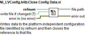
NI_LVConfig.lvlib:Close Config Data.vi: Writes data to the platform-independent configuration file identified by refnum and then closes the reference to that file.
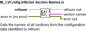
NI_LVConfig.lvlib:Get Section Names.vi: Gets the names of all sections from the configuration data identified by refnum.
NI_LVConfig.lvlib:Open Config Data.vi: Opens a reference to the configuration data found in a platform-independent configuration file.

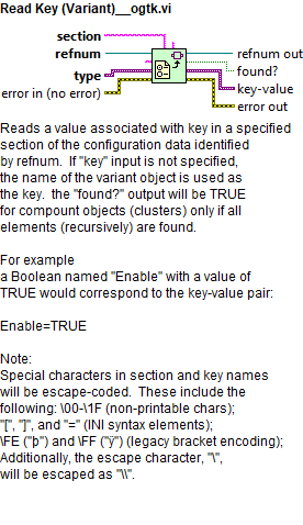
Read Key (Variant)__ogtk.vi: Reads a value associated with key in a specified section of the configuration data identified by refnum. If “key” input is not specified, the name of the variant object is used as the key. the “found?” output will be TRUE for compount objects (clusters) only if all elements (recursively) are found. For example a Boolean named “Enable” with a value of TRUE would correspond to the key-value pair: Enable=TRUE Note: Special characters in section and key names will be escape-coded. These include the following: \00-\1F (non-printable chars); “[”, “]”, and “=” (INI syntax elements); \FE (“þ”) and \FF (“ÿ”) (legacy bracket encoding); Additionally, the escape character, “\”, will be escaped as “\”.
Telemetry logging task
This task is the one obtaining the data from the PXI. This task does two main things:
Read the data from the PXI and store it in memory. To be accessible by the rest of tasks/windows that may need the data.
Save the read data in TDMS format locally, as said before for 2 days. This files after a certain time are zipped (conversion to *.zip) to reduce space in the hard drive.
For doing this the variables are read from the PXI using the URLs defined at the Topic Telemetry configuration file. Part of this task is also configured using the “HMIConfig.xml” file, as it is considered to be general configuration and not topic specific configuration. The configuration values obtained from that file are:
File_Saving_directory_path: this is a relative path starting at the project location.
HMIWindowsTelemetryVariables_file_path: here the absolute path to the Window Telemetry configuration file is specified.
TelemetryTopics_file_path: here the absolute path to the Topic Telemetry configuration file is specified.
DataAcquieringLoopFrequency_ms: this value corresponds to the timing of the acquisition loop of the telemetry variables in mili seconds.
Telemetry_Decimate_Save: this value is used to avoid overloading when saving, this value is used to divide the saving into bigger arrays to save into the TDMS, the value corresponds to the iteration multiple of the data acquisition loop. This means that with a default value of 10 the arrays with 50 values obtained every 50 ms are saved every (10*50ms) 500 ms in arrays of 500 values size.
TelemetryTaskConfig.DataHistoryDays: this value corresponds to the maximum value of stored data in days. The default value is 2, this means that files older than 2 days will be erased.
TelemetryTaskConfig.SecondsToLeaveUnZipped: this value, in seconds, corresponds to the minimum time for TDMS files to be unzipped. This means that the last TDMS to be zipped will be the actual time minus this value. With the default value of 3600, means that there will be unzipped files for the last hour.
Task process
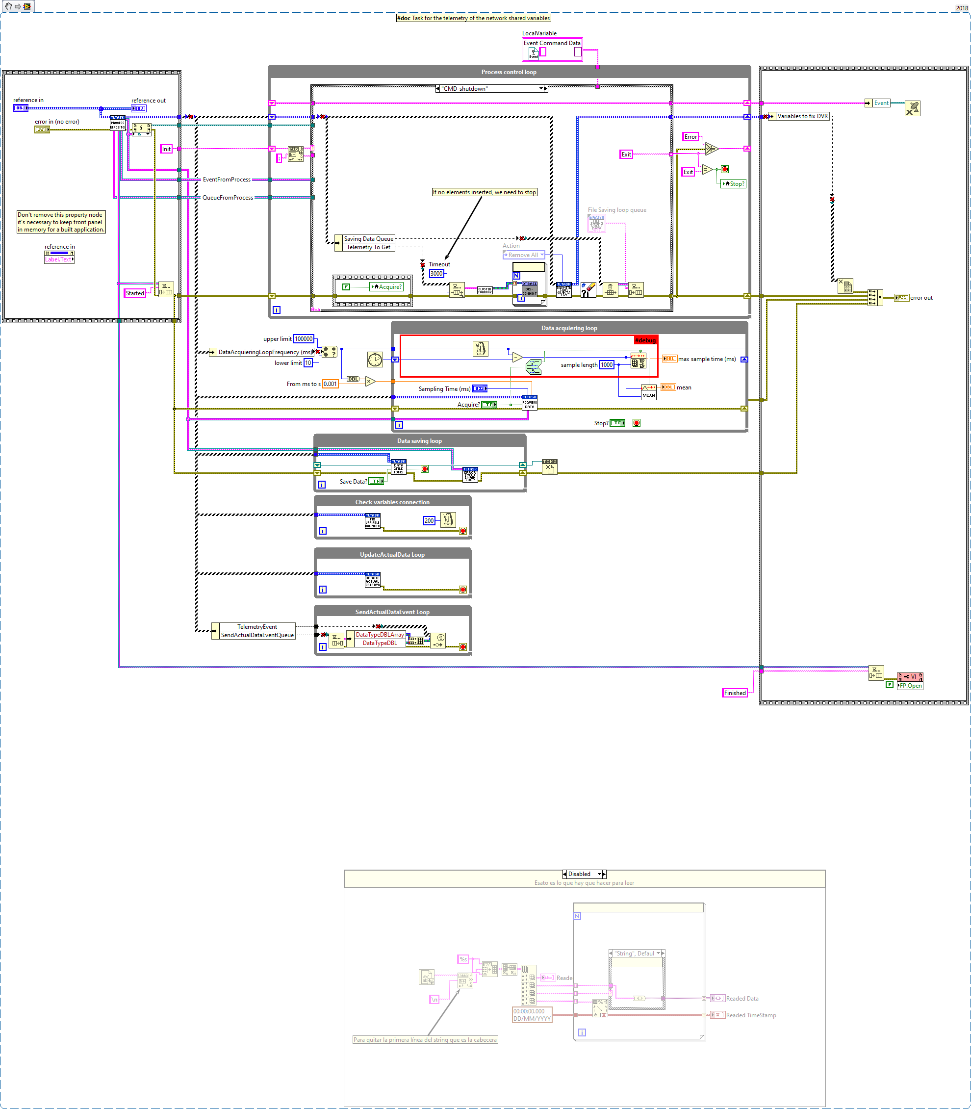
This task was created using the NI GOOP Developing Suite, this task is object oriented and the communication between methods is done using queues and user events. The task main is contained in the process.vi, here there are 6 loops.
The loop on top is used for CMD reception.
The Data acquiring loop, is the one reading the network shared variables from the PXI.
The Data saving loop, is the one that writes the acquired data to TDMS.
The Check variables connection loop, this loop is used to reconnect the variables that may fail when read in the Data acquiring loop.
UpdateActualData loop, this loop gets the data from the Data acquiring loop and stores it into a DVR to be accessible by other tasks.
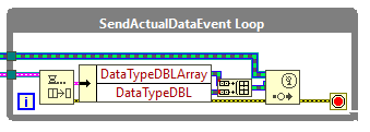
SendActualDataEvent loop, this event gets the data from the Data acquiring loop and publishes an event with the DBL and DBL Array data types. This event is used in the windows only, to plot the values into graphs.
CMD Reception loop
This loop receives the CMDs from the methods and passes the required actions to the corresponding loop.
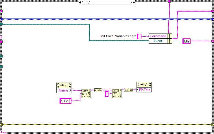
Init
Here the initialization actions are executed.
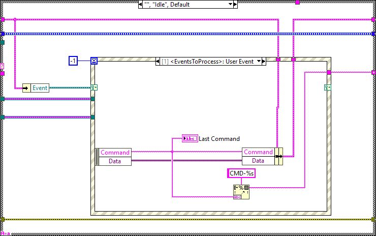
Idle
This state is executed constantly after executing every new CMD, here the events created at the methods are received and executed in the next iteration.
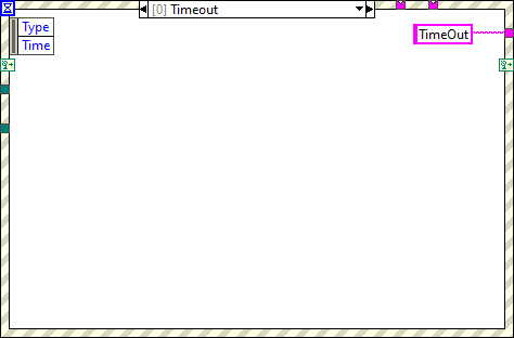
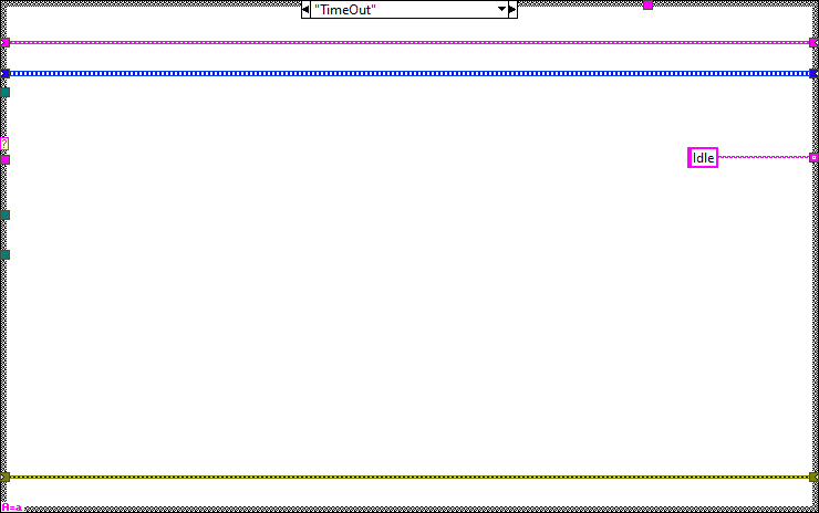
Timeout
This state is executed when there is something that must be executed in the specified timeout of the Idle state event structure.
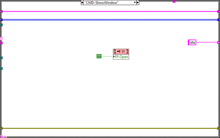
CMD-ShowWindow
This state is used to show the front panel of the process.
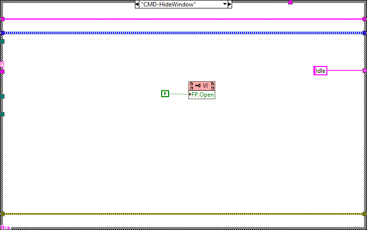
CMD-HideWindow
This state is used to hide the front panel of the process.
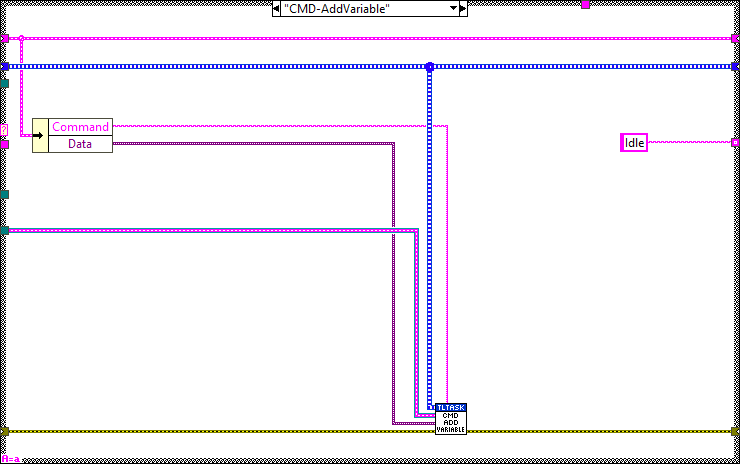
CMD-AddVariable
Verify if the variable exists, if not the variable is connected and added other ways not.
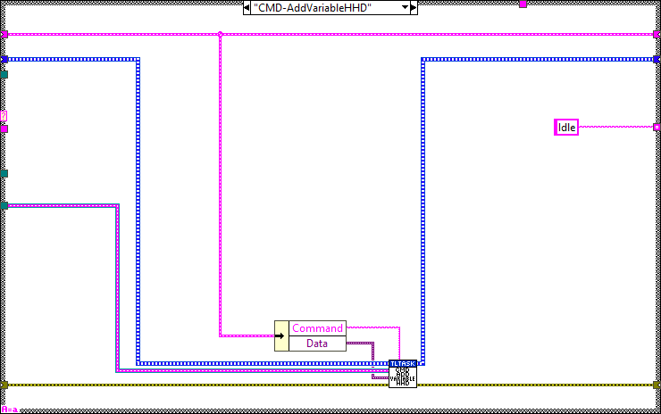
CMD-AddVariableHHD
Verify if the variable exists, if not the variable is connected but NOT ADDED, this would be made by another method that will add only the variables needed for the loaded window.
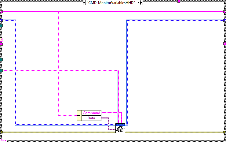
CMD-MonitorVariablesHHD
Verify if the variable exists, if not the variable is added other ways not. If monitor is true, the variable is added for monitoring if false its removed from monitoring.
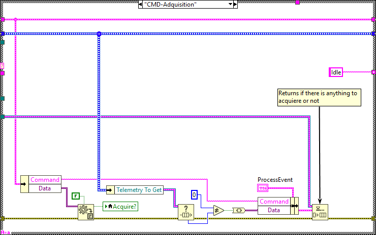
CMD-Adquisition
Manage the variables acquisition, start or stop it.
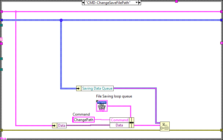
CMD-ChangeSaveFilePath
Change the path for saving the telemetry, send the new path to the Data Saving Loop.
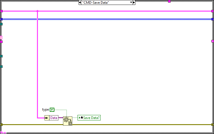
CMD-SaveData
Manage the data saving, start or stop it.
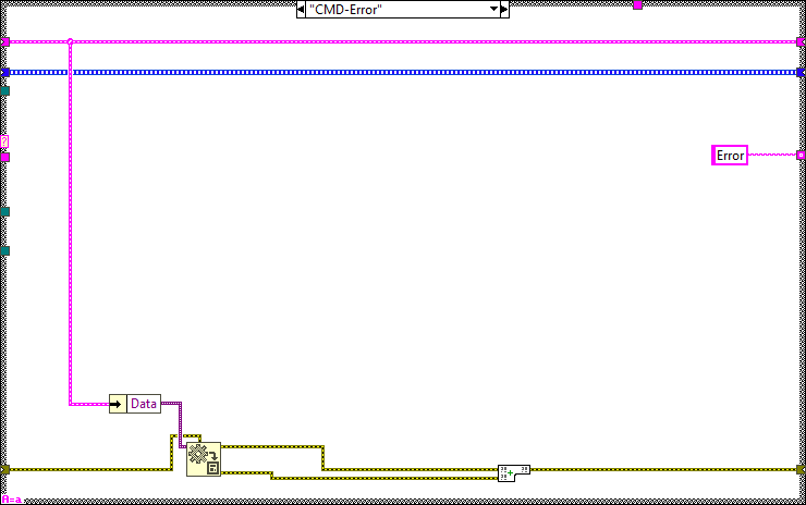
CMD-Error
Get the error and set it to the error line, this will make the task to go to the Error case and process it there.
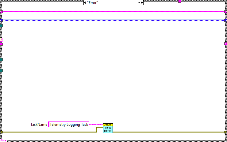
Error
Send the error from the error line to the Error Task.
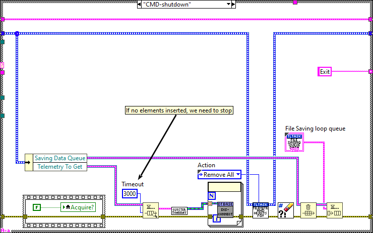
CMD-Shutdown
Here the actions to shutdown the task are executed.
Data Acquiring Loop
The Data acquiring loop, is the one reading the network shared variables from the PXI. This loop then sends the data to the other loops to manage it as intended in each case.

Data Saving Loop
The Data saving loop, is the one that writes the acquired data to TDMS.

Check Variables Connection Loop
The Check variables connection loop, this loop is used to reconnect the variables that may fail when read in the Data acquiring loop.

Update Actual Data Loop
Update Actual Data loop, this loop gets the data from the Data acquiring loop and stores it into a DVR to be accessible by other tasks.
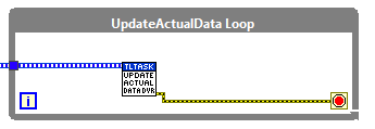
Send Actual Data Event loop
Send Actual Data Event loop, this event gets the data from the Data acquiring loop and publishes an event with the DBL and DBLarray data types. This event is used in the windows only, to plot the values into graphs.
Task methods
Here the available methods for this task are explained.
AddVariableMethodChoice
This method selects which add variable method must be used depending on the current device Global variable (EUI or HHD).

AssignInitClasses
Here the telemetry variable objects are initialized using the TelemetryTopicDefinitions.

ChangeFileSavingPath
Change the file path to save the telemetry data

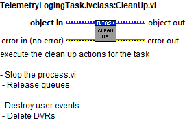
CleanUp
execute the clean up actions for the task
- Stop the process.vi
- Release queues
- Destroy user events
- Delete DVRs
GetAllTelemetry
Returns the data from the actualDataDVR

GetTelemetryDataURL
Returns the data from the queue

ManageAdquisition
Manages the adquisition of the telemetry task

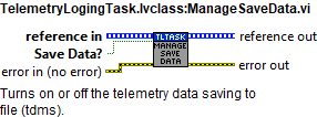
ManageSaveData
Turns on or off the telemetry data saving to file (tdms).
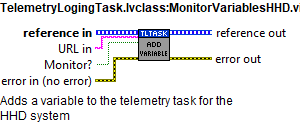
MonitorVariablesHHD
Adds a variable to the telemetry task for the HHD system
Read TelemetryEvent
Gets the TelemetryEvent reference from the class object

TelemetryFilePathCreation
Generates the path to save the telemetry data for each 10 minutes

TelemetryLogingTask_Init
Initialize the telemetry process. Also includes the compression of old telemetry files (TDMS) onto zip files.

TCP Telemetry task
This task is responsible of sending all the needed telemetry to the CSC over TCP.
Task process
This task was created using the NI GOOP Developing Suite, this task is object oriented and the communication between methods is done using queues and user events. The task main is contained in the process.vi, here there are two loops. The loop on top is used for CMD reception and the bottom one for publishing. This process has only one instance that manages all the telemetry data.
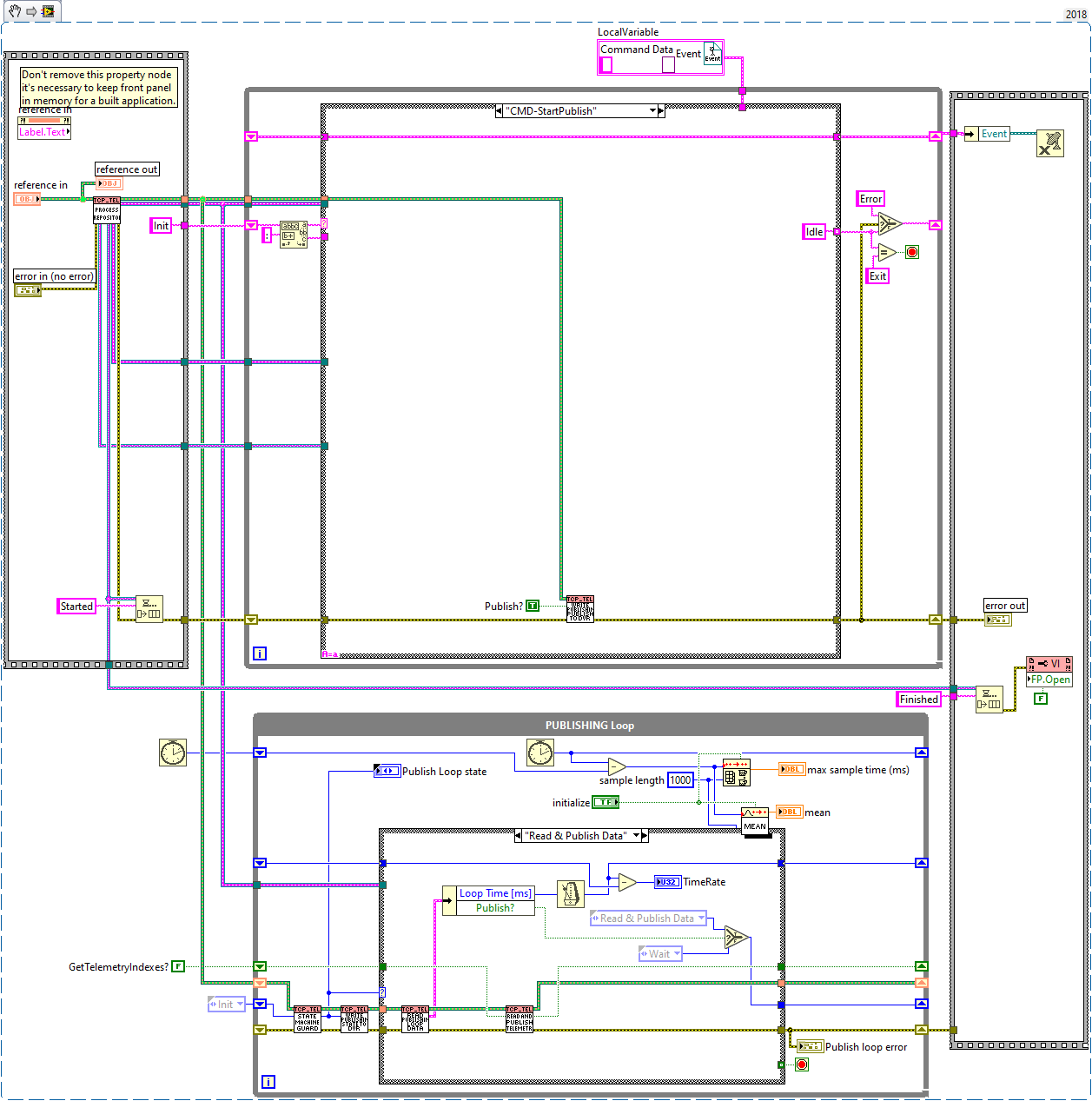
CMD Reception loop
This loop receives the CMDs from the methods and passes the required actions to the publishing loop.
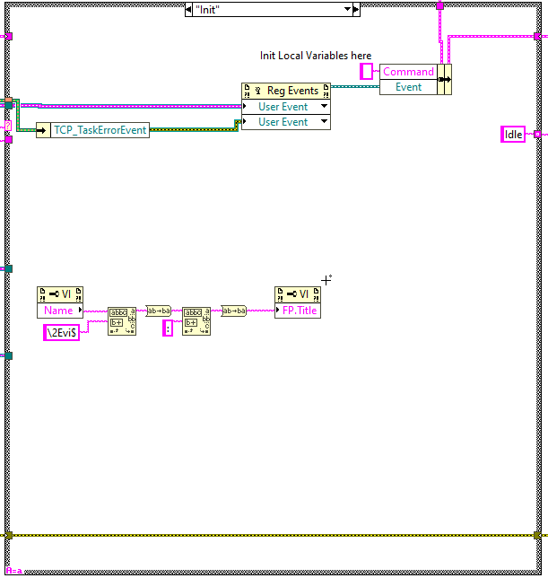
Init
Here the initialization actions are executed.
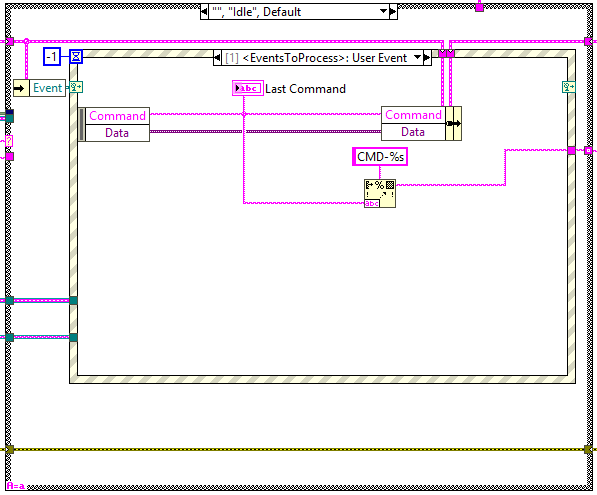
Idle
This state is executed constantly after executing every new CMD, here the events created at the methods are received and executed in the next iteration.
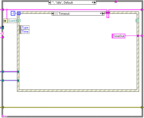
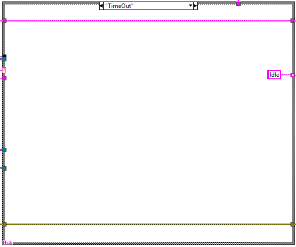
Timeout
This state is executed when there is something that must be executed in the specified timeout of the Idle state event structure, see Figure \ref{figurefifty-onef7565b74148bf04cd1f4f1fb69d642c1}.
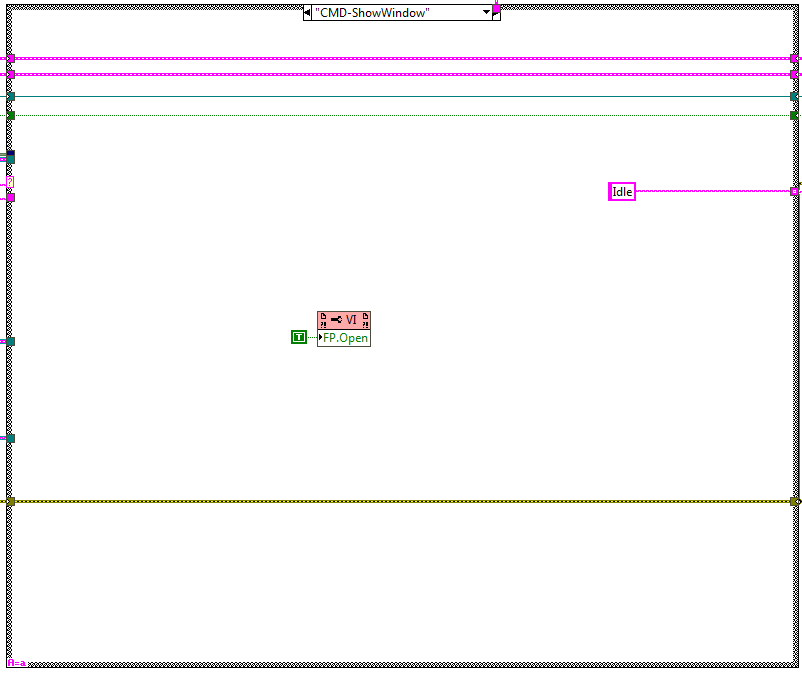
CMD-ShowWindow
This state is used to show the front panel of the process.
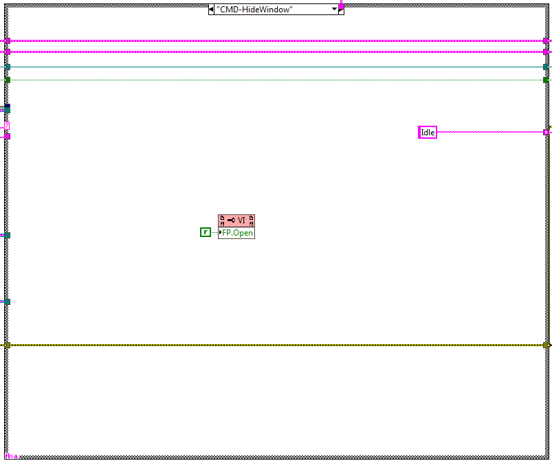
CMD-HideWindow
This state is used to hide the front panel of the process.
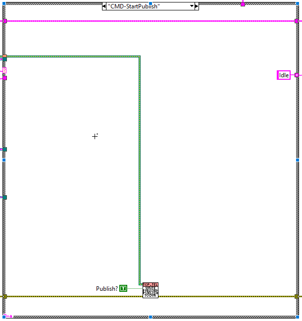
CMD-StartPublish
This state is executed when the StartPublish method is used. Here the TCP publishing loop is started.
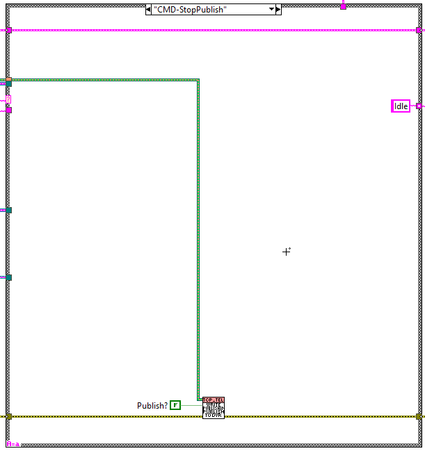
CMD-StopPublish
This state is executed when the StopPublish method is used. Here the TCP publishing loop is stopped.
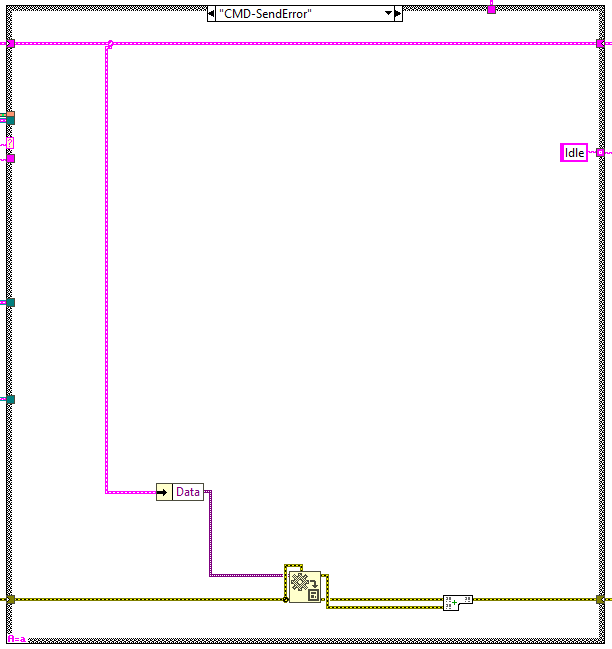
SendError
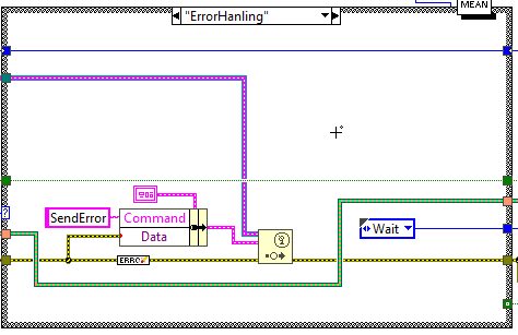
This state is executed when the SendError CMD is received, this CMD is sent by the TCP publishing loop at the error handling state. Here the received error is set to the error line to enter the error case in the next iteration.
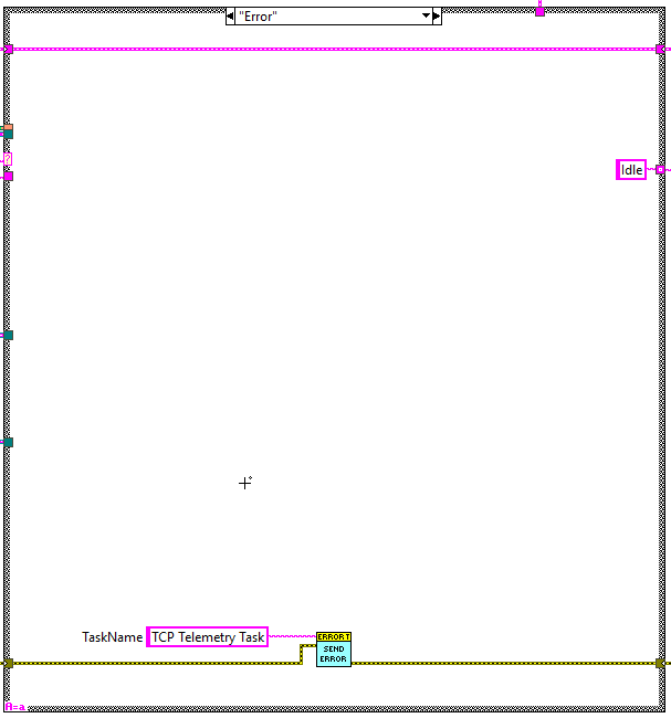
Error
This state is reached when an error occurred at the loop or is received from the publishing loop. Here the error is posted to the error task.
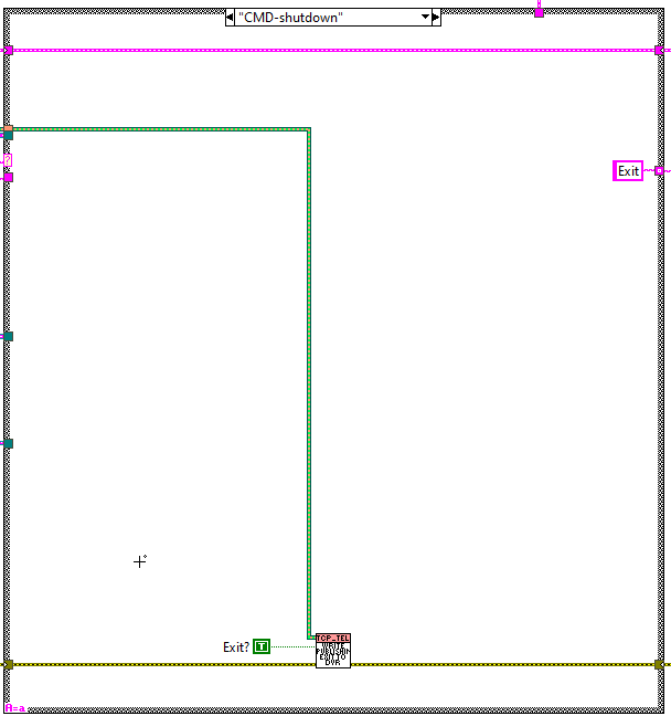
CMD-Shutdown
This state is reached when the shutdown CMD is received. This loop is used to stop the TCP publishing loop.
TCP Publishing loop
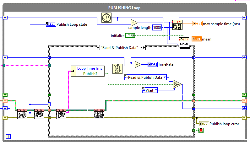
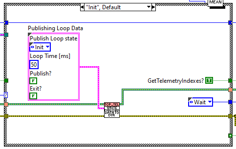
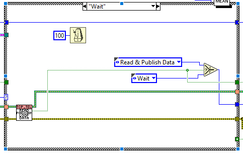
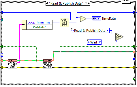
This loop is responsible of publishing the telemetry over TCP. This loop contains a very simple state machine with 5 states, each of them is explained in the upcoming sections.
Init
This state is launched at start. Here the DVR with the loop data is initialized to default values. The next state is launched: Wait.
Wait
Here the data for the loop is read from the DVR.
If Publish?=True the next state is launched: Read&PublishData
If Publish?=False the next state is launched: Wait
Read&PublishData
Here the data for the loop is read from the DVR and the main task of this loop is done: read telemetry and publish it over TCP.
If Publish?=True the next state is launched: Read&PublishData
If Publish?=False the next state is launched: Wait
ErrorHandling
The state machine guard launches this state if there is an error at the error line from the previous state. Here the error is posted to the CMD reception loop.
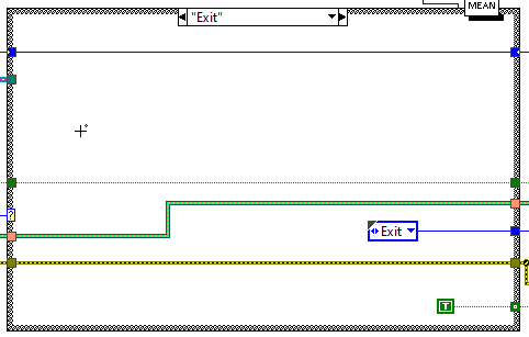
Exit
This state is launched from the guard and launches when the loop data DVR exit is set to true. Here the loop is stopped.
Task methods
Here the available methods for this task are explained.
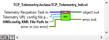
TCP_Telemetry_Init
This VI is used to launch the process, to do so some inputs are required:
Telemetry Task Reference: here the reference to the telemetry task is given to be able of reading the telemetry from inside the task.
Telemetry URL config file path in: Topic Telemetry configuration file.
HMIconfig XML File Path in: here the general configuration file “HMIConfig.xml” must be given.
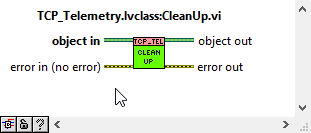
CleanUp
This VI is used to stop the task and release all the references generated for this task.
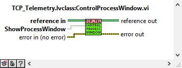
ControlProcessWindow
This VI is used to show or hide the process front panel. Depending on the ShowProcessWindow control value.
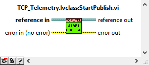
StartPublish
This VI is used to start publishing data over TCP.
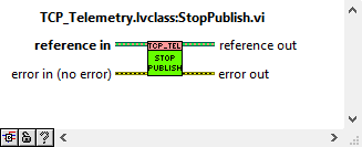
StopPublish
This VI is used to start publishing data over TCP.
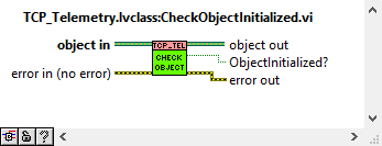
CheckObjectInitialized
This VI is used to check if the object was initialized or not.
Testing
There is a project created to test that both tasks work properly. This project is located inside the “HMIComputers” repository inside the TCP_Telemetry folder, relative path: “HMIComputers\TCP_Telemetry\TestTCP_Task\TestTCP_Task\TestTCP_Task.lvproj”.
Note: To run this test the “jki_labs_tool_vi_tester” package must be installed, it can be found in the VI package manager or here: https://www.vipm.io/package/jki_labs_tool_vi_tester/
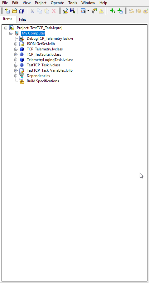
To execute the test, follow these steps:
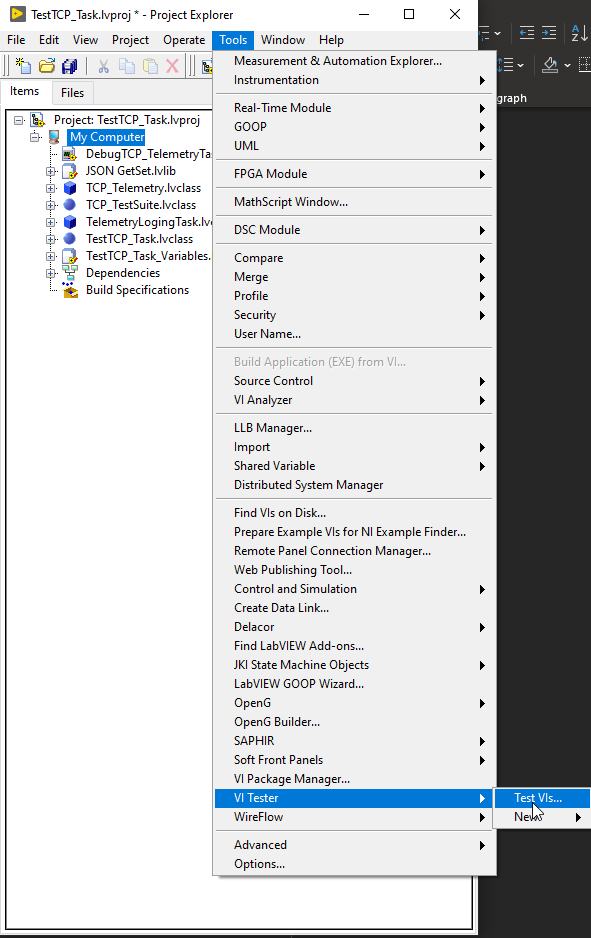
Go to “Tools >> VI Tester >> Test Vis…” (see Figure \ref{figureseventy-three82e7710b0a2bfe47ecc3d9133390240e}).
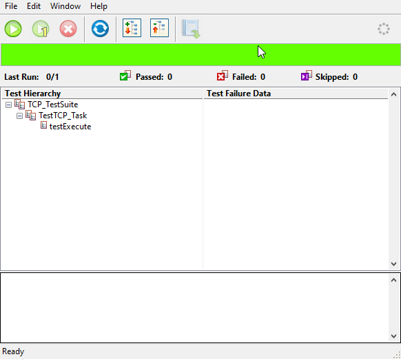
After opening the VI Tester the window should look like Figure \ref{figureseventy-four8bb99b74ac6211d5f5566e390b3f9cdf}.
Run the test, click on the green play button, see Figure \ref{figureseventy-five51ed8c8cb3aaade4e0dfff636a7142e9}.
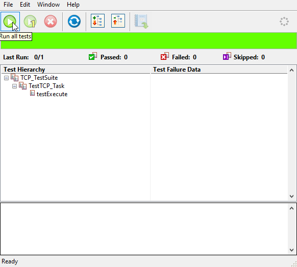
Check test results, the result must be passed as shown in Figure \ref{figureseventy-six7342723fa19ba888fc82330a69980371}.
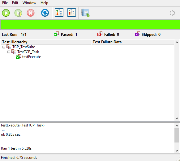
Close the VI Tester and the TestTCP_Task.lvproj.