This is a Windows 10 machine where LabVIEW simulators and tools will run.
It is currently a Virtual Machine located on a hypervisor under the url tma-windows.ls.lsst.org.
It can be accessed on the lsst-wap network or by using the anyconnect or openconnect vpn.
Access can be granted by filing an IHS ticket with IT.
Also, a specific tool to manage to simulator in the Speedgoat is running here.
Labview
You need your NI account to be granted access by IT to activate a license on the LabVIEW License Server located on nlm-labview-1.lsst.org
Tools needed:
LabVIEW 2020 - installer zips located on Pavo or on NI’s website with NI SSP enabled account
LabVIEW License manager - Download on NI’s website
JKI LabVIEW VI Package Manager - JKI account needed - Free edition is good enough
NI MAX - included with LabVIEW
LabVIEW packages listed in the table in section 4 of 3151_MCS_0036 - All of the packages that the installer comes with except for NI statemachine which is now a VIPM package.
VI packages listed in section 4 of the deployment document
In the Windows Machine some simulators and some tools are running.
Start installing the Force EtherCAT Variables installer, that will install the LabVIEW runtime needed in many other tools and simulators.
This tool allows writing data to EtherCAT variables to other simulators using a TCP based custom protocol.
The value written using this tool will overwrite any set value, so any slave value will be overwritten with the written value.
The source code and more documentation about configuration can be found in forceethercatvars(gitlab).
This tool allows reading and writing data from network shared variables to other simulators and uses a TCP based custom protocol.
The source code and more documentation about configuration can be found in readvariables(gitlab).
This is a simulator for the bosch power supply, this simulator manages the digital inputs that tell the TMA PXI the status of the power supply.
The source code and more documentation about configuration can be found in boschpowersupplysimulator(gitlab)
This is a simulator for the thermal behavior of the phase motors, this simulator manages the analog inputs that tell the TMA PXI the temperatures of the motors and uses this values to control the output signal of the valve to manage the temperature of them.
The source code and more documentation about configuration can be found in motorthermalmodelsimulator(gitlab).
This is a simulator for the phase power supply, this simulator manages the analog inputs that tell the TMA PXI the status of the power supply.
The source code and more documentation about configuration can be found in phasepowersupplysimulator(gitlab).
Follow next steps to deploy this software:
If the installer or executable is available continue to step 6
Clone the repository in the link above
Open the project PhasePowerSupplySimulator.lvproj
Go to “Build Specifications” and right click in “Executable” to select “Build”
When build finishes go to build folder and copy all files and folder
Paste compilation files to desired destination in Windows Machine
This software allows to simulate the behavior of some subsystem limit switches.
Those limits could be part of safety system or EtherCAT distributed IOs.
The source code and more documentation about configuration can be found in simulatelimits(gitlab).
Follow next steps to deploy this software:
If the installer or executable is available continue to step 6
Clone the repository in the link above
Open the project SimulateLimits.lvproj
Go to “Build Specifications” and right click in “SimulateLimits” to select “Build”
When build finishes go to build folder and copy all files and folder
Paste compiled files to desired destination in the Windows Machine
Open the “data” folder and open “GeneralConfiguration.xml”
Change the first path of the field TCP_senders_configuration_Path to point to ForceECATVars_TCP_SenderConfig.xml file in the same data folder.
Change dim=’[X]’ to dim=’[1]’ for “TCP_senders_configuration_Path” and for “LimitsDefinition” tags.
We are only using the first configured limit because you need the safety full simulator with PILZ hardware to use other limits, when you get this hardware (perhaps you have one on the submit) we can download code to it and use those other limits.
This is a simulator for the temperature controller of the cabinets, this simulator contains the simulator of the different temperature controllers available all over the telescope.
The source code and more documentation about configuration can be found in cabinet-az0001(gitlab).
Follow next steps to deploy this software:
If the installer or executable is available continue to step 6
Clone the repository in the link above
Open the project cabinetTemperatureControllerSimulator.lvproj
Go to “Build Specifications” and right click in “Executable” to select “Build”
When build finishes go to build folder and copy all files and folder
Paste compilation files to desired destination in Windows Machine
Run cabinetTemperatureControllerSimulator.exe
The cabinets included in this simulator are:
TMA_AX_DZ_CBT_0001 (Phase Main Power Cabinet)
TMA_AZ_CS_CBT_0001 (TEK Mount Control System cabinet - MCS)
TMA_AZ_PD_CBT_0001 (Azimuth Power Distribution)
TMA_AZ_PD_TRM_0001 (Isolation transformer)
TMA_EL_PD_CBT_0001 (Elevation Power Distribution 1)
TMA_EL_PD_CBT_0002 (Elevation Power Distribution 2)
This is a simulator for the extensions of the deployable platforms, this simulator manages the digital inputs that tell the Safety system the status of the extensions of the deployable platforms.
The source code and more documentation about configuration can be found in dpextensionssimulator(gitlab).
Follow next steps to deploy this software:
If the installer or executable is available continue to step 6
Clone the repository in the link above
Open the project DPextensionsSimulator.lvproj
Go to “Build Specifications” and right click in “Executable” to select “Build”
When build finishes go to build folder and copy all files and folder
Paste compilation files to desired destination in Windows Machine
This is a simulator for the Oil Supply System (OSS), this simulator contains a modbus server that connects to the TMA PXI to transmit the status of the OSS.
The source code and more documentation about configuration can be found in oilsupplysystemsimulator(gitlab).
Follow next steps to deploy this software:
If the installer or executable is available continue to step 6
Clone the repository in the link above
Open the project OilSupplySystemSimulator.lvproj
Go to “Build Specifications” and right click in “Executable” to select “Build”
When build finishes go to build folder and copy all files and folder
Paste compilation files to desired destination in Windows Machine
This provides the motion model for the TMA using specialized hardware.
The Speedgoat Manager will handle loading the model and managing the configurations.
Before starting to deploy the model, make sure that the SpeedgoatManager is running.
Install matlab 2020a with the following dependencies
In the Linux Machine the secondary axis simulators and the robot framework tests are running.
This is a Virtual Machine running on a hypervisor that is located under tma-centos.ls.lsst.org.
It can be accessed either on the lsst-wap network or by using the anyconnect vpn.
Access can be granted by filing an IHS ticket with Vera C. Rubin Observatory IT.
The “PXI” is actually a desktop tower running Alma Linux 8 with a VM running NIRT Linux.
You’ll need to install the ethercat library and configure it correctly in order to see the CRIO client that’s connected to the desktop server. See NI Linux RT.
This is the PXI where the control code for all subsystems is running.
To be able to configure the TMA PXI, the development PC should be configured as shown in the deployment document.
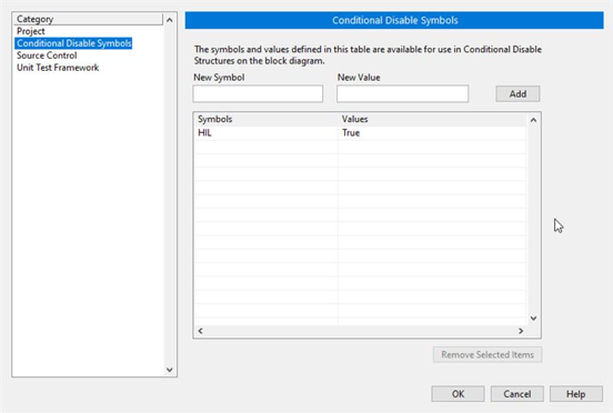
Ensure that in the project properties the Conditional Disable Symbol “HIL” is set to “True”
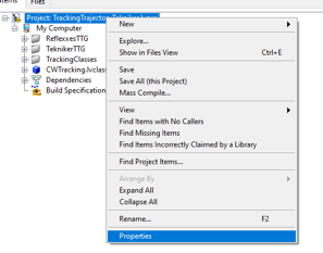
Right click in the project an select properties
In the opened window go to Conditional Disable Symbols page and set the value for HIL symbol to “True”.
Continue with steps 3.a to 3.c of the point 6.2 in the Deployment document.
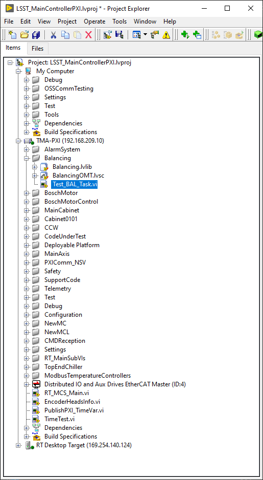
Open the RT_MCS_Main.vi (for testing the whole project)
To test just one subsystem some specific test VIs can be found inside the corresponding subsystem folder. For example the Balancing specific test VI shown below:
Run the VI
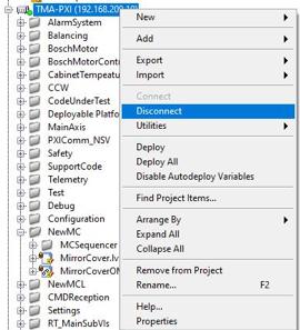
When the vi is deployed to the target, disconnect the target
The “PXI” is actually a desktop tower running Alma Linux 8 with a VM running NIRT Linux. See NI Linux RT
This is the PXI where the control code for the main axes is running.
To be able to configure the AXES PXI, the development PC should be configured as shown in the deployment document
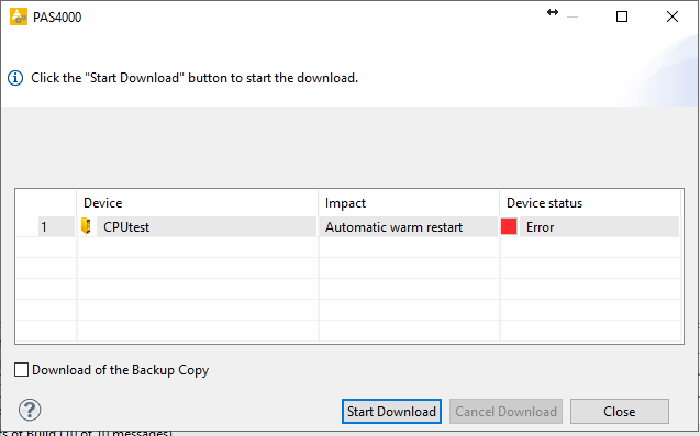
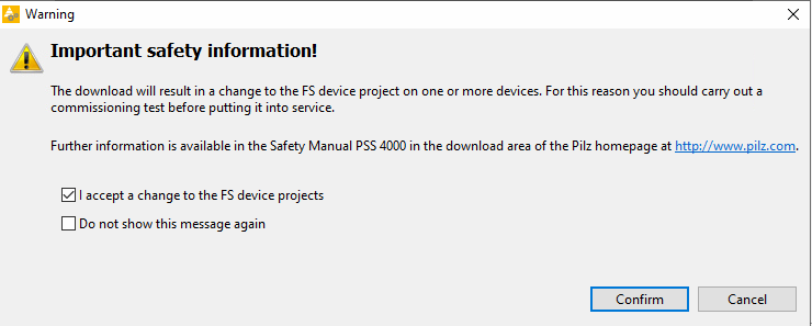
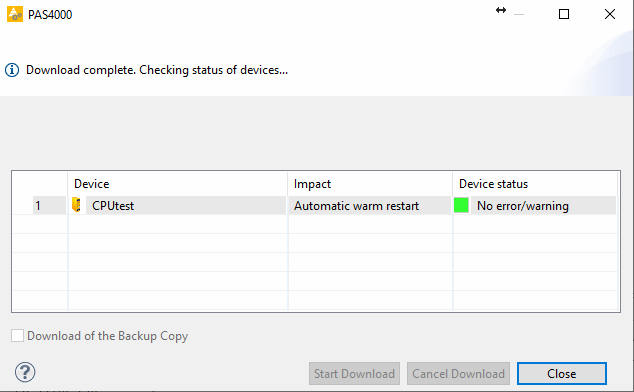
The code that runs on the PILZ controller to simulate the behavior of the TMA Interlock System.
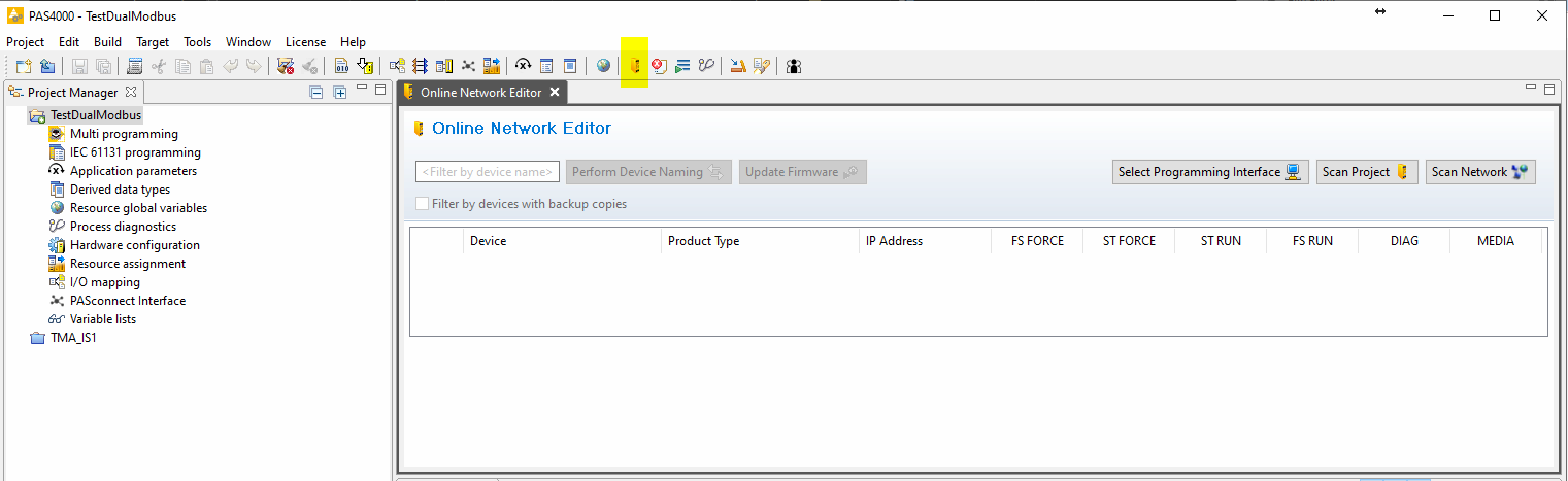
The source code and more documentation about configuration can be found in testdualmodbus(gitlab)
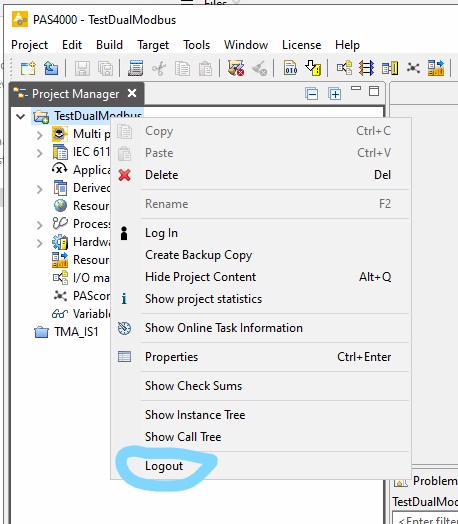
Open the “TestDualModbus” project with PAS4000 version 1.18.0
Activate the “TestDualModbus”
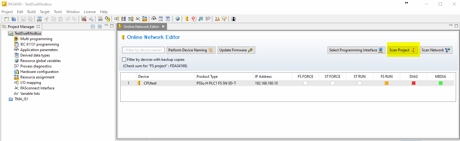
Open the online network editor
Scan project to scan the network to verify that the PILZ CPU is connected