10. ATS Deployment Guide
Table of Contents
10.1. Introduction
This document describes the procedure run the automatic test system. The document will show the hardware configuration in section 3 and software deployment in section 4.
10.2. Reference documents
Nº Document code Version 1 Deployment document 3151_MCS_0036 1.0 Todo
obtain the table information from the ts_xml table
10.3. Hardware configuration
In this section the needed hardware and its configuration is explained.
10.3.1. Windows Machine
This is a Windows 10 machine where LabVIEW simulators and tools will run. Also, a specific tool to manage to simulator in the Speedgoat is implemented here. Nothing special is needed in this machine.
10.3.2. Speedgoat
The Speedgoat is used to simulate the main axis behaviour in real time.
Speedgoat
Serial Number: 4539 (ItemID 109200)
Options:
- CPUCorei74200 (ItemID 109211)
- SSD500GB (ItemID 109048)
- Input/Output modules:
- Ethercat Slaves, IO750 (x2) (ItemID 2B7506)
- IO 306
Software configuration will be downloaded using Tekniker made tool.
10.3.3. PILZ CPU
This will be used to simulate and test safety software
- PIlz PSSu 4000 ref 314070
- PSSu E F 4DI-T
- PSSu E F 4DO 0.5-T
The configuration of hardware is part of the project where the code is included, some configuration will be explained in section 4.
10.4. Software deployment
Each hardware has different software parts, and some hardware had more than one software part. In the following sections each hardware element is explained.
10.4.1. Windows Machine
In the Windows Machine some simulators and some tools are running. Start installing the Force EtherCAT Variables installer, that will install the LabVIEW runtime needed in many other tools and simulators.
10.4.1.2. Force EtherCAT Variables
This tool allows writing data to EtherCAT variables to other simulators using a TCP based custom protocol. The value written using this tool will overwrite any set value, so any slave value will be overwritten with the written value. The source code and more documentation about configuration can be found in https://gitlab.tekniker.es/aut/projects/3151-LSST/hil/forceethercatvars. Follow next steps to deploy this software
- If the installer is available continue to step 6
- Clone the repository in the link above
- Open the project ForceEtherCATVars.lvproj
- Go to “Build Specifications” and right click in “ForceIOs” to select “Build”
- Go to “Build Specifications” and right click in “ForceEtherCatVars Installer” to select “Build”
- When compilation is finished, open location and copy the “Volume” folder to Windows Machine
- Install the tool using the “install.exe”
- Run ForceIOs.exe.
10.4.1.3. Simulate limits
This software allows to simulate the behaviour of some subsystem limits switches. Those limits could be part of safety system or EtherCAT distributed IOs. The source code and more documentation about configuration can be found in https://gitlab.tekniker.es/aut/projects/3151-LSST/hil/simulatelimits Follow next steps to deploy this software
- If the installer or executable is available continue to step 6
- Clone the repository in the link above
- Open the project SimulateLimits.lvproj
- Go to “Build Specifications” and right click in “SimulateLimits” to select “Build”
- When build finishes go to build folder and copy all files and folder
- Paste compiled files to desired destination in Windows Machine
- Open the “data” folder and open “GeneralConfiguration.xml”
- Change the first path of the field TCP_senders_configuration_Path to point to ForceECATVars_TCP_SenderConfig.xml file in the same data folder.
- Change dim=’[X]’ to dim=’[1]’ for “TCP_senders_configuration_Path” and for “LimitsDefinition” tags. We are only using the first configured limit because you need the safety full simulator with PILZ hardware to use other limits, When you get this hardware (perhaps you have one on the submit) we can download code to it and use those other limits.
- Run SimulateLimits.exe
10.5. TMA PXI
This is the PXI where the control code for all subsystems is running. To be able to configure the TMA PXI, the development PC should be configured as shown in the deployment document
Download the PXI repository: https://gitlab.tekniker.es/aut/projects/3151-LSST/LabVIEWCode/PXIController
Open the LSST_MainControllerPXI.lvproj.
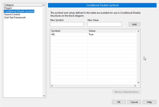
Ensure that in the project properties the Conditional Disable Symbol “HIL” is set to “True”
- Right click in the project an select properties
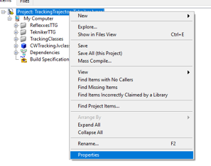
- In the opened window go to Conditional Disable Symbols page and set the value for HIL symbol to “True”.
Continue with steps 3.a to 3.c of the point 6.2 in the Deployment document.
Open the RT_MCS_Main.vi
Run the VI
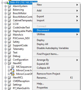
When the vi is deployed to the target, disconnect the target
- Right click TMA_PXI target and click Disconnect