ATS Deployment Guide
Table of Contents
Introduction
This document describes the procedure run the automatic test system. The document will show the hardware configuration in section 3 and software deployment in section 4.
Reference documents
| N° | Document | code | Version |
|---|---|---|---|
| 1 | Deployment document | 3151_MCS_0036 | 1.0 |
Todo
obtain the table information from the ts_xml table
Hardware configuration
In this section the needed hardware and its configuration is explained.
Windows Machine
This is a Windows 10 machine where LabVIEW simulators and tools will run. Also, a specific tool to manage to simulator in the Speedgoat is implemented here. Nothing special is needed in this machine.
Speedgoat
The Speedgoat is used to simulate the main axis behavior in real time.
Speedgoat
Serial Number: 4539 (ItemID 109200)
Options:
- CPUCorei74200 (ItemID 109211)
- SSD500GB (ItemID 109048)
- Input/Output modules:
- Ethercat Slaves, IO750 (x2) (ItemID 2B7506)
- IO 306
Software configuration will be downloaded using Tekniker made tool.
Software deployment
Each hardware has different software parts, and some hardware had more than one software part. In the following sections each hardware element is explained.
Windows Machine
In the Windows Machine some simulators and some tools are running. Start installing the Force EtherCAT Variables installer, that will install the LabVIEW runtime needed in many other tools and simulators.
Force EtherCAT Variables
This tool allows writing data to EtherCAT variables to other simulators using a TCP based custom protocol. The value written using this tool will overwrite any set value, so any slave value will be overwritten with the written value. The source code and more documentation about configuration can be found in https://gitlab.tekniker.es/aut/projects/3151-LSST/hil/forceethercatvars.
Follow next steps to deploy this software:
- If the installer is available continue to step 6
- Clone the repository in the link above
- Open the project ForceEtherCATVars.lvproj
- Go to “Build Specifications” and right click in “ForceIOs” to select “Build”
- Go to “Build Specifications” and right click in “ForceEtherCatVars Installer” to select “Build”
- When compilation is finished, open location and copy the “Volume” folder to Windows Machine
- Install the tool using the “install.exe”
- Run ForceIOs.exe.
BoschPowerSupplySimulator
This is a simulator for the bosch power supply, this simulator manages the digital inputs that tell the TMA PXI the status of the power supply. The source code and more documentation about configuration can be found in https://gitlab.tekniker.es/aut/projects/3151-LSST/hil/boschpowersupply/boschpowersupplysimulator
Follow next steps to deploy this software:
- If the installer or executable is available continue to step 6
- Clone the repository in the link above
- Open the project BoschPowerSupplySimulator.lvproj
- Go to “Build Specifications” and right click in “Executable” to select “Build”
- When build finishes go to build folder and copy all files and folder
- Paste compilation files to desired destination in Windows Machine
- Run BoschPowerSupplySimulator.exe
motorThermalModelSimulator
This is a simulator for the thermal behaviour of the phase motors, this simulator manages the analog inputs that tell the TMA PXI the temperatures of the motors and uses this values to control the output signal of the valve to manage the temperature of them. The source code and more documentation about configuration can be found in https://gitlab.tekniker.es/aut/projects/3151-LSST/hil/motorthermalmodel/motorthermalmodelsimulator
Follow next steps to deploy this software:
- If the installer or executable is available continue to step 6
- Clone the repository in the link above
- Open the project motorThermalModelSimulator.lvproj
- Go to “Build Specifications” and right click in “Executable” to select “Build”
- When build finishes go to build folder and copy all files and folder
- Paste compilation files to desired destination in Windows Machine
- Run motorThermalModelSimulator.exe
PhasePowerSupplySimulator
This is a simulator for the phase power supply, this simulator manages the analog inputs that tell the TMA PXI the status of the power supply. The source code and more documentation about configuration can be found in https://gitlab.tekniker.es/aut/projects/3151-LSST/hil/phasepowersupply/phasepowersupplysimulator
Follow next steps to deploy this software:
- If the installer or executable is available continue to step 6
- Clone the repository in the link above
- Open the project PhasePowerSupplySimulator.lvproj
- Go to “Build Specifications” and right click in “Executable” to select “Build”
- When build finishes go to build folder and copy all files and folder
- Paste compilation files to desired destination in Windows Machine
- Run PhasePowerSupplySimulator.exe
Simulate limits
This software allows to simulate the behavior of some subsystem limits switches. Those limits could be part of safety system or EtherCAT distributed IOs. The source code and more documentation about configuration can be found in https://gitlab.tekniker.es/aut/projects/3151-LSST/hil/simulatelimits
Follow next steps to deploy this software:
- If the installer or executable is available continue to step 6
- Clone the repository in the link above
- Open the project SimulateLimits.lvproj
- Go to “Build Specifications” and right click in “SimulateLimits” to select “Build”
- When build finishes go to build folder and copy all files and folder
- Paste compiled files to desired destination in the Windows Machine
- Open the “data” folder and open “GeneralConfiguration.xml”
- Change the first path of the field TCP_senders_configuration_Path to point to ForceECATVars_TCP_SenderConfig.xml file in the same data folder.
- Change dim=’[X]’ to dim=’[1]’ for “TCP_senders_configuration_Path” and for “LimitsDefinition” tags. We are only using the first configured limit becauseyou need the safety full simulator with PILZ hardware to use other limits, When you get this hardware (perhaps you have one on the submit) we can download code to it and use those other limits.
- Run SimulateLimits.exe
cabinetTemperatureControllerSimulator
This is a simulator for the temperature controller of the cabinets, this simulator contains the simulator of the different temperature controllers available all over the telescope. The source code and more documentation about configuration can be found in https://gitlab.tekniker.es/aut/projects/3151-LSST/hil/cabinettemperaturecontroller/cabinet-az0001
Follow next steps to deploy this software:
- If the installer or executable is available continue to step 6
- Clone the repository in the link above
- Open the project cabinetTemperatureControllerSimulator.lvproj
- Go to “Build Specifications” and right click in “Executable” to select “Build”
- When build finishes go to build folder and copy all files and folder
- Paste compilation files to desired destination in Windows Machine
- Run cabinetTemperatureControllerSimulator.exe
The cabinets included in this simulator are:
- TMA_AX_DZ_CBT_0001 (Phase Main Power Cabinet)
- TMA_AZ_CS_CBT_0001 (TEK Mount Control System cabinet - MCS)
- TMA_AZ_PD_CBT_0001 (Azimuth Power Distribution)
- TMA_AZ_PD_TRM_0001 (Isolation transformer)
- TMA_EL_PD_CBT_0001 (Elevation Power Distribution 1)
- TMA_EL_PD_CBT_0002 (Elevation Power Distribution 2)
extensionSimulatorForDP
This is a simulator for the extensions of the deployable platforms, this simulator manages the digital inputs that tell the Safety system the status of the extensions of the deployable platforms. The source code and more documentation about configuration can be found in https://gitlab.tekniker.es/aut/projects/3151-LSST/hil/dpextensionssimulator
Follow next steps to deploy this software:
- If the installer or executable is available continue to step 6
- Clone the repository in the link above
- Open the project DPextensionsSimulator.lvproj
- Go to “Build Specifications” and right click in “Executable” to select “Build”
- When build finishes go to build folder and copy all files and folder
- Paste compilation files to desired destination in Windows Machine
- Run extensionSimulatorForDP.exe
OilSupplySystemSimulator
This is a simulator for the Oil Supply System (OSS), this simulator contains a modbus server that connects to the TMA PXI to transmit the status of the OSS. The source code and more documentation about configuration can be found in https://gitlab.tekniker.es/aut/projects/3151-LSST/hil/oilsupplysystem/oilsupplysystemsimulator
Follow next steps to deploy this software:
- If the installer or executable is available continue to step 6
- Clone the repository in the link above
- Open the project OilSupplySystemSimulator.lvproj
- Go to “Build Specifications” and right click in “Executable” to select “Build”
- When build finishes go to build folder and copy all files and folder
- Paste compilation files to desired destination in Windows Machine
- Run OilSupplySystemSimulator.exe
SpeedgoatManager
This is a simulator tool used for the robot framework tests to connect to the Speedgoat. The source code and more documentation about configuration can be found in https://gitlab.tekniker.es/aut/projects/3151-LSST/hil/speedgoat
Follow next steps to deploy this software:
- Get the latest version of the compiled code from here: https://gitlab.tekniker.es/aut/projects/3151-LSST/hil/speedgoat/speedgoatmanagerbinaries
- Paste it to the windows machine
Linux Machine
In the Linux Machine the secondary axis simulators and the robot framework tests are running.
secondaryAxisSil
This is a simulator for the secondary axes (bosch axes), this simulator contains a modbus server that connects to the TMA PXI to transmit the status of each of the axes. The source code and more documentation about configuration can be found in https://gitlab.tekniker.es/aut/projects/3151-LSST/hil/secondaryaxis/secondaryaxissil
Follow the steps defined in the secondaryAxisSilREADME.
robotFramework
This refers to the automatic test framework the installation steps to setup the environment for robot framework is explained here: https://gitlab.tekniker.es/aut/projects/3151-LSST/test/robotframework/-/wikis/Installation
The source code and more documentation can be found in https://gitlab.tekniker.es/aut/projects/3151-LSST/test/robotframework
TMA PXI
This is the PXI where the control code for all subsystems is running. To be able to configure the TMA PXI, the development PC should be configured as shown in the deployment document
Download the PXI repository: https://gitlab.tekniker.es/aut/projects/3151-LSST/LabVIEWCode/PXIController
Open the LSST_MainControllerPXI.lvproj.
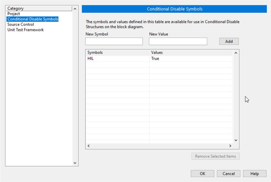
Ensure that in the project properties the Conditional Disable Symbol “HIL” is set to “True”
- Right click in the project an select properties
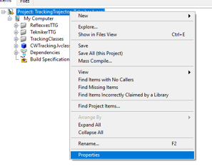
- In the opened window go to Conditional Disable Symbols page and set the value for HIL symbol to “True”.
Continue with steps 3.a to 3.c of the point 6.2 in the Deployment document.
Open the RT_MCS_Main.vi (for testing the hole project)
To test just one subsystem some specific test VIs can be found inside the corresponding subsystem folder. For example the Balancing specific test VI shown bellow:
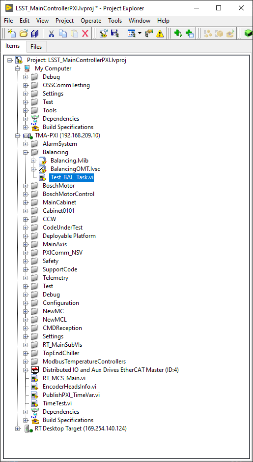
Run the VI
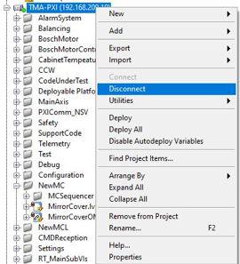
When the vi is deployed to the target, disconnect the target
- Right click TMA_PXI target and click Disconnect
AXES PXI
This is the PXI where the control code for the main axes is running. To be able to configure the AXES PXI, the development PC should be configured as shown in the deployment document
Download the PXI repository: https://gitlab.tekniker.es/aut/projects/3151-LSST/LabVIEWCode/PXIController
Open the LSST_MainControllerPXI.lvproj.
Ensure that in the project properties the Conditional Disable Symbol “HIL” is set to “True”
- Right click in the Axes PXI an select properties
- In the opened window go to Conditional Disable Symbols page and set the value for HIL symbol to “True”.
Continue with steps 3.a to 3.c of the point 7.2 in the Deployment document.
Open the MAIN_AxesPXI.vi
Run the VI
When the vi is deployed to the target, disconnect the target
- Right click AXES_PXI target and click Disconnect
Safety code deployment
The code that runs on the PILZ controller to simulate the behaviour of the TMA IS. The source code and more documentation about configuration can be found in https://gitlab.tekniker.es/aut/projects/3151-LSST/hil/testdualmodbus
Open the “TestDualModbus” project with PAS4000 version 1.18.0
Activate the “TestDualModbus”
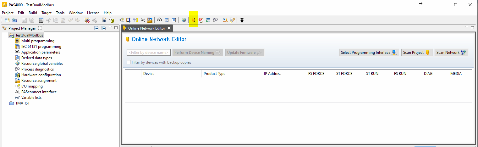
Open the online network editor
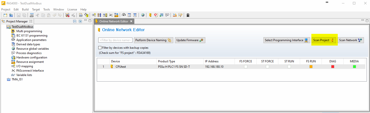
Scan project to scan the network to verify that the PILZ CPU is connected
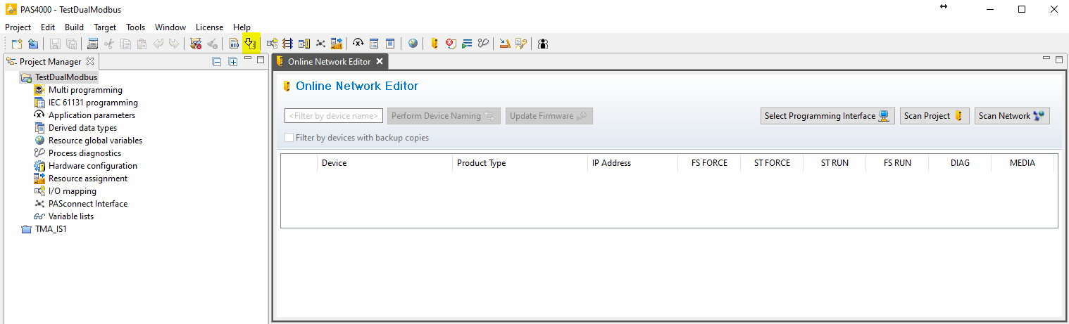
Close the online network editor
Download the project
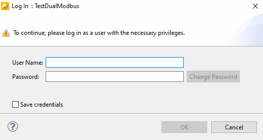
Open the Project downloader:
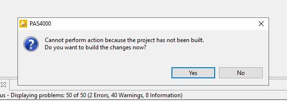
If asked to build changes say YES
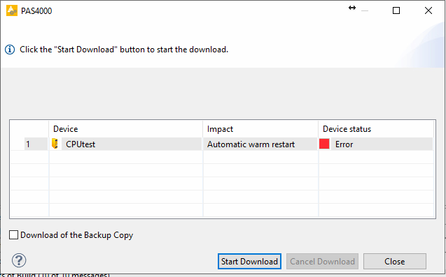
Start download:
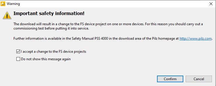
Confirm download:
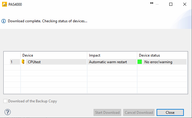
Download completed:
Logout:
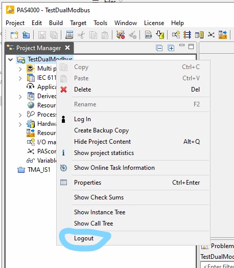
Close the PAS4000