This is a Windows 10 machine where LabVIEW simulators and tools will run.
It is currently a Virtual Machine located on a hypervisor under the url tma-windows.ls.lsst.org.
It can be accessed on the lsst-wap network or by using the anyconnect vpn.
Access can be granted by filing an IHS ticket with IT.
Also, a specific tool to manage to simulator in the Speedgoat is implemented here.
Labview
Need to be granted access by IT to activate a license on the LabVIEW License Server located on lsst-pdm
Warning
lsst-pdm is being replaced sometime in the future.
New location is yet to be determined.
Tools needed:
LabVIEW 2018 SP1 - installer zips located on Pavo
LabVIEW License manager - downloadable on NI website
JKI LabVIEW VI Package Manager - JKI account needed
NI MAX
LabVIEW packages listed in the table in section 4 of 3151_MCS_0036
VI packages listed in section 4
Tekniker made VIs - location of the files to be solved eventually
Each hardware has different software and in some cases more than one running on it.
In the following section, the software is installed on the computers.
In the Windows Machine some simulators and some tools are running.
Start installing the Force EtherCAT Variables installer, that will install the LabVIEW runtime needed in many other tools and simulators.
This tool allows writing data to EtherCAT variables to other simulators using a TCP based custom protocol.
The value written using this tool will overwrite any set value, so any slave value will be overwritten with the written value.
The source code and more documentation about configuration can be found in https://gitlab.tekniker.es/aut/projects/3151-LSST/hil/forceethercatvars.
Follow next steps to deploy this software:
If the installer is available continue to step 6
Clone the repository in the link above
Open the project ForceEtherCATVars.lvproj
Go to “Build Specifications” and right click in “ForceIOs” to select “Build”
Go to “Build Specifications” and right click in “ForceEtherCatVars Installer” to select “Build”
When compilation is finished, open location and copy the “Volume” folder to Windows Machine
This tool allows reading and writing data from network shared variables to other simulators and uses a TCP based custom protocol.
The source code and more documentation about configuration can be found in https://gitlab.tekniker.es/aut/projects/3151-LSST/hil/readvariables
Follow next steps to deploy this software:
If the installer or executable is available continue to step 6
Clone the repository in the link above
Open the project ReadVariables.lvproj
Go to “Build Specifications” and right click in “Executable” to select “Build”
When build finishes go to build folder and copy all files and folder
Paste compilation files to desired destination in Windows Machine
Open the “data” folder and open “WriteReadVarConfig.xml”.
Change the path of the field TCP_configuration_file to point to TCP_ServerConfig.xml file in the same data folder.
This is a simulator for the thermal behaviour of the phase motors, this simulator manages the analog inputs that tell the TMA PXI the temperatures of the motors and uses this values to control the output signal of the valve to manage the temperature of them.
The source code and more documentation about configuration can be found in https://gitlab.tekniker.es/aut/projects/3151-LSST/hil/motorthermalmodel/motorthermalmodelsimulator
Follow next steps to deploy this software:
If the installer or executable is available continue to step 6
Clone the repository in the link above
Open the project motorThermalModelSimulator.lvproj
Go to “Build Specifications” and right click in “Executable” to select “Build”
When build finishes go to build folder and copy all files and folder
Paste compilation files to desired destination in Windows Machine
This software allows to simulate the behavior of some subsystem limits switches. Those limits could be part of safety system or EtherCAT distributed IOs.
The source code and more documentation about configuration can be found in https://gitlab.tekniker.es/aut/projects/3151-LSST/hil/simulatelimits
Follow next steps to deploy this software:
If the installer or executable is available continue to step 6
Clone the repository in the link above
Open the project SimulateLimits.lvproj
Go to “Build Specifications” and right click in “SimulateLimits” to select “Build”
When build finishes go to build folder and copy all files and folder
Paste compiled files to desired destination in the Windows Machine
Open the “data” folder and open “GeneralConfiguration.xml”
Change the first path of the field TCP_senders_configuration_Path to point to ForceECATVars_TCP_SenderConfig.xml file in the same data folder.
Change dim=’[X]’ to dim=’[1]’ for “TCP_senders_configuration_Path” and for “LimitsDefinition” tags. We are only using the first configured limit becauseyou need the safety full simulator with PILZ hardware to use other limits, When you get this hardware (perhaps you have one on the submit) we can download code to it and use those other limits.
This is a simulator for the extensions of the deployable platforms, this simulator manages the digital inputs that tell the Safety system the status of the extensions of the deployable platforms.
The source code and more documentation about configuration can be found in https://gitlab.tekniker.es/aut/projects/3151-LSST/hil/dpextensionssimulator
Follow next steps to deploy this software:
If the installer or executable is available continue to step 6
Clone the repository in the link above
Open the project DPextensionsSimulator.lvproj
Go to “Build Specifications” and right click in “Executable” to select “Build”
When build finishes go to build folder and copy all files and folder
Paste compilation files to desired destination in Windows Machine
In the Linux Machine the secondary axis simulators and the robot framework tests are running.
This is a Virtual Machine running on a hypervisor that is located under tma-centos.ls.lsst.org.
It can be accessed either on the lsst-wap network or by using the anyconnect vpn.
Access can be granted by filing an IHS ticket with Vera C. Rubin Observatory IT.
This is the PXI where the control code for all subsystems is running. To be able to configure the TMA PXI, the development PC should be configured as shown in the deployment document
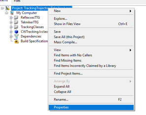
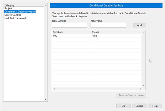
Ensure that in the project properties the Conditional Disable Symbol “HIL” is set to “True”
Right click in the project an select properties
In the opened window go to Conditional Disable Symbols page and set the value for HIL symbol to “True”.
Continue with steps 3.a to 3.c of the point 6.2 in the Deployment document.
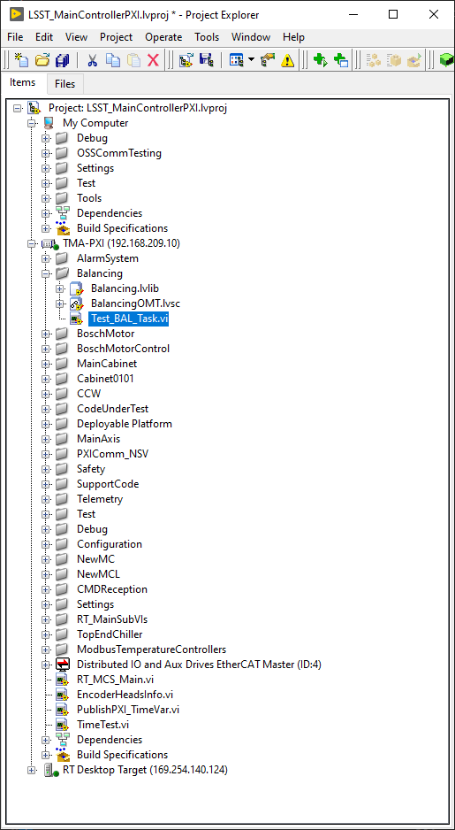
Open the RT_MCS_Main.vi (for testing the hole project)
To test just one subsystem some specific test VIs can be found inside the corresponding subsystem folder. For example the Balancing specific test VI shown bellow:
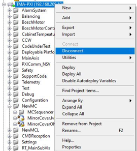
Run the VI
When the vi is deployed to the target, disconnect the target
This is the PXI where the control code for the main axes is running.
To be able to configure the AXES PXI, the development PC should be configured as shown in the deployment document